|
|
|
TOPIC:
Project "Better XR311" 11 years 3 months ago #16609
|
Thought it was about time I'd better start writing this up, before I forget what I've been up to with it!
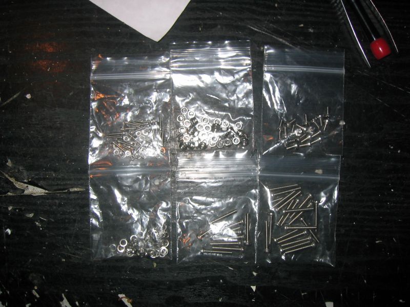
Not a lot actually done/assembled yet, but as you will see, there's been some considerable work involved thus far. Not really sure how far it's going to go, or indeed, where it might go theme-wise, as I haven't really settled on an idea for bodywork yet. Anyway, once upon a time, a nice man called Jonny asked me if I wanted any Cheetah/XR311 giblets. I had them off him with a view to putting something together for a laugh, & so this project was born! Anyone who's ever owned a Cheetah or XR311 will already know just how fragile these cars are (Particularly if you tread on them, eh Jonny!). To name a few problems with them, obviously the hugely fragile body, the brittle torsion bars for the suspension, weak gearbox, odd size flanged bronze bearings & the huge amount of slop in the steering linkages/pivots. I could add to the list indefinately... When the box of entrails arrived, I had a quick sort through with the aid of the manual, to find out exactly what was there & what wasn't, had a think about ease of making the missing bits, then decided to have a bash at it. 1st job was to have a count-up of fasteners & get them ordered. I decided to go metric with this one, as it was never going to be very original. I don't know what posessed me, but I opted for slotted cheese head screws (Stainless), I think because at the time I was unsure how original I wanted it to look. In hindsight, I wish I'd gone for socket button screws - they look miles better & there isn't the issue of non-magnetic slotted screws being a nightmare to install! Below, nearly a car's-worth of sorted bits, & 3 quid's-worth of fasteners 
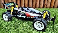
Bought some boxed wheels off Ebay, not 100% sure I'll be using them yet, depends on what body I go for 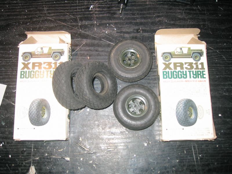
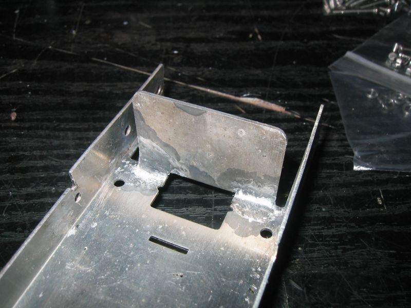
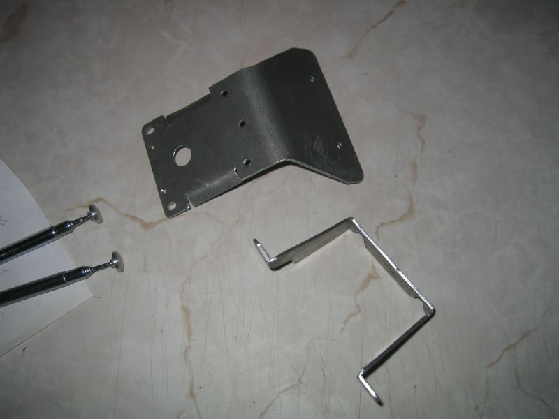
If you've already read my resto of the other XR311, you'll already know that as I was taking it to bits, I had also been merrily copying the parts that were missing for this one. For this reason, the pictures might not follow the build order, as a lot of the bits I'd already made before I started putting anything together.... Follow the manual then I guess.... Page 1, put bits on the chassis. To do this, I need a chassis... I robbed the good one for the other car, so the other car's busted chassis had to be fixed, which involved attempting to weld the steering servo mounting plate back on. You really don't want to do this, it wouldv'e been bad enough if it was thin steel, let alone ally! Ok, it's not neat, but it was never going to be. It's stuck, it appears to be strong, & after some grinding back I think it'll do 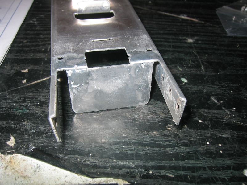
Needed the hex bushes for the sliding front body mount clip (Not even sure if I'm going to use that yet) so made some 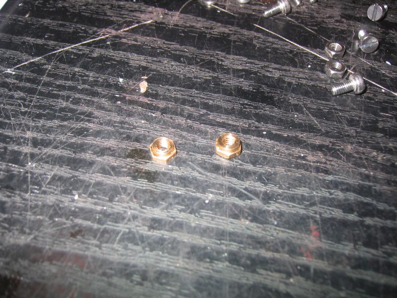
Next bit in the manual is front suspension & steering stuff. Needed 3-off those brass spacer tubes to assemble the front suspension, so made those. Didn't have any suitable tube, so ended up boring out some brass rod instead. Also in the pic is a pair of uPVC torsion bars I made for the other car, drive hexes, rear wheel spacers, polyethylene plugs for the gearbox & cover, & a reinforcing collar for one of the drive cups 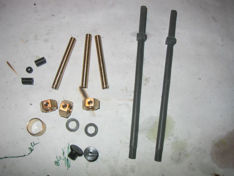
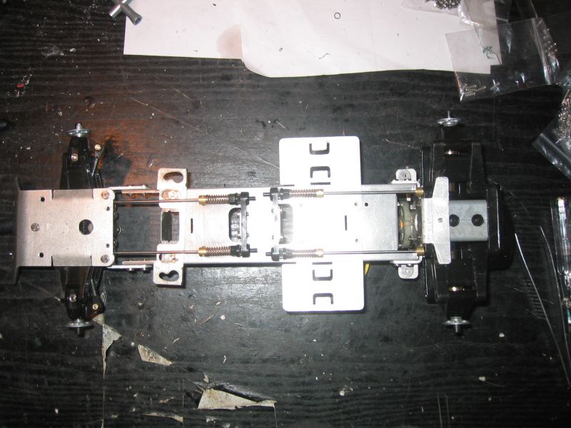
Put the front suspension & steering components together, & mounted the subframe to the main chassis, complete with some posh torsion bars I'd come up with 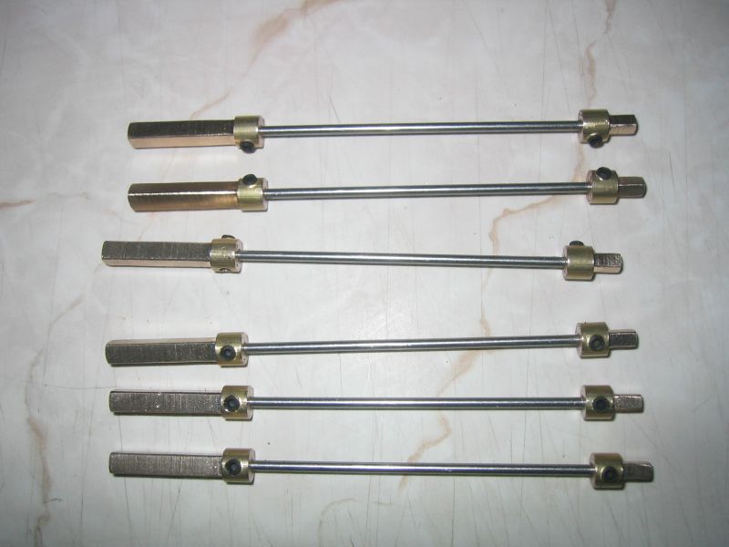
The end-squares are brass & are grub-screwed onto 2mm high-tensile stainless wire (Bicycle spokes). The onds of the wire are flatted to prevent rotation. The brass collars are cross-drilled to allow an allen key or small screwdriver to be inserted, for ease of adjustment. The end splines & springs are XR311 kit parts. These work beautifully!
Custom F2
...
Hilux crossmember drawing
...
F2 axle drawing
...
Quattro radio lid
...
Holiday Buggy motor bracket drawing
...
Quattro resto
...
HitnMiss engine
...
Wild Willy resto
...
Mardave Cobra resto
...
Thunder Dragon resto
...
Grasshopper resto
...
XR311 resto
...
Modded XR311
...
Carbon 25th scratch build
|
|
|
Please Log in to join the conversation. |
Re: Project "Better XR311" 11 years 3 months ago #16649
|
I'd already made a front bumper & rear body mount/rollbar, copied them whilst dismatling the other car. You'll also see in the pic that I'd been making Rx aerial tips that day too.
There was very little wear in the front suspension/steering bits, so that lot got put together as it was with no modification, using 20mm long screws as per the manual. Horrible... screws are far too long & all the moving parts have a hilarious amount off free-play. Sure you need some clearance for free-moving parts, but I measure 1.10mm gap between the knuckles & C-hubs (I've poked a steel rule in the gap for the pic, & that's a loose-fit too!). If it was going to be original I'd ignore it, but it's not, so I felt it should be made right 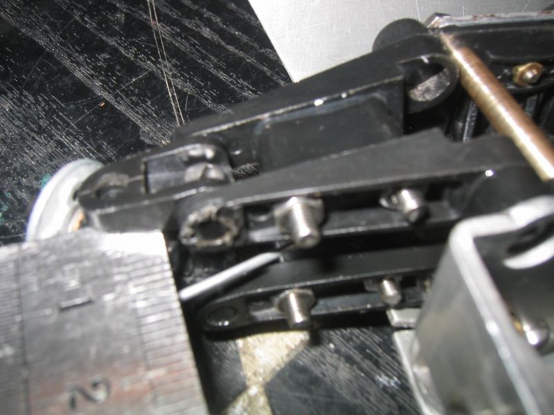
Took it to bits, shortened the screws, milled 1.05mm off the C-hub square spacers (To get rid of the gap) & put it back together. Gave it a wiggle, tons of slop in the steering, despite the link holes etc being totally unworn. The worst of the slop appeared to be related to the servo-saver bits, so I addressed that next. Servo-saver spring is a sloppy fit on the relay-arm thing, so I wrapped a layer of sticky aluminium tape around it. Better... The pin on the steering "rack" is far too small, so there's slop there too. T sort this, I found a suitable piece of Tx aerial tube, which I CA glued onto the pin to make its diameter bigger. Better still... 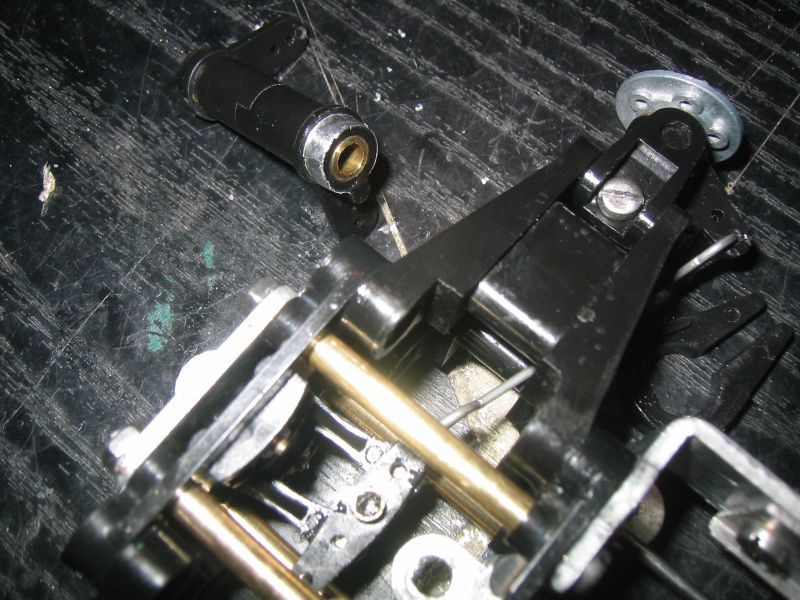
Put it all back together again & gave it another wiggle. Much better, but still sloppy. The remainder of the slop in the steering linkages was coming from the wire trackrods, who's ends have a relatively large radiused eye rather than the Z-bend we see on other Tamiyas where bent wire rods attach to plain holes - these circular "eyes" tend to ride-up through the holes rather than moving the linkage during operation. The holes also have too much clearance on the wire which also doesn't help. To get around this, I ditched the plain wire trackrods & made up some proper ones, using generic 2mm plastic rose-joints & M2 studding (Cut down some fully threaded servo case screws for the studding). Fitted my new trackrods, smashing, no slop whatsoever! You move the servo link & the hubs turn left/right the same amount, both in the same direction at once - it's not often (Ever) you can say that about XR311 steering! 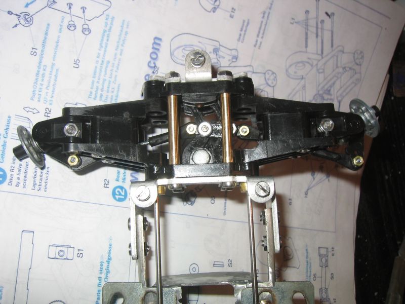
At this point, I'd already fitted ballraces to the front hubs & had partially assembled the gearbox, also with ballraces. The available ballraces similar to the Tamiya bronze bushings require shimming to make the assemblies fit together properly (This is a story in itself). For anyone planning to try ballracing an XR311/Cheetah, all I can say is only do it if you have the means to come up with suitable collars & shims to be able to use them. The car hasn't been designed to allow direct replacement of the bronze with ballraces, & in several locations you will discover that the bronze bearing is acting as both radial & axial bearings (ie both bearing proper AND thrust type). There is also an issue in that the bronze bearings aren't a direct swap for ballraces dimensionally (More on that later). Rambling aside, the ballraces for the front stub axles are MF85ZZ, 5x8x2.5 flanged, metal sheilded. The flange on these bearings is 9dia x 0.6 thick, verses 10dia x 1mm thick for the bronze. The overall thickness of the ballrace varies depending on what type of seals are fitted. In this case, 2.5mm overall thickness with metal shields, verses 4mm overall for the bronze. These discrepancies had the overall result that the front stub axles are too long... (See gap between bearing & circlip groove) 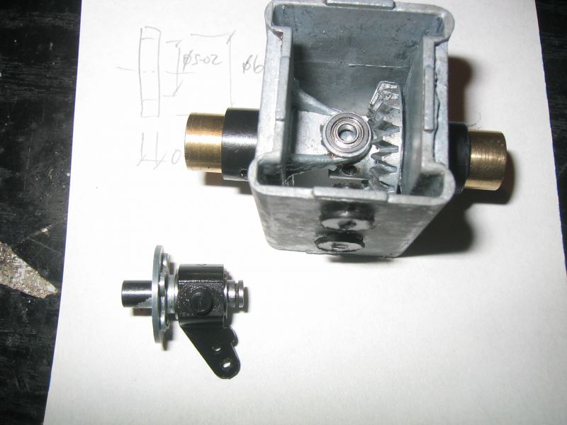
I'll come back to the gearbox & bearings, but to get around the front stub axle problem I had to make some collar/shim things. It's like this, when mounting something up to ballraces, you have to have some form of shoulder on the part, so that it only bears on the ballrace outer OR inner race, NOT both at the same time, or you get friction/binding. You remember me saying that in some locations the bronze is acting as both a proper AND thrust bearing? Yep, front stub axles are one of these locations - the bronze is a proper (Radial) bearing for the shaft, & a thrust bearing (Axial) for the wheel-plate & circlip. SO, if I'm fitting ballraces, the outer race will bear on the plastic knuckle (By way of the bearing flange), but the circlip & wheel-plate will need something so they only bear on the bearing inner race (So a plain washer would be too big). I also need to fill the gaps whilst I'm at it. Machined up some collar/spacer thingies, 6mm O/D x 5.02mm I/D x 0.75mm thick 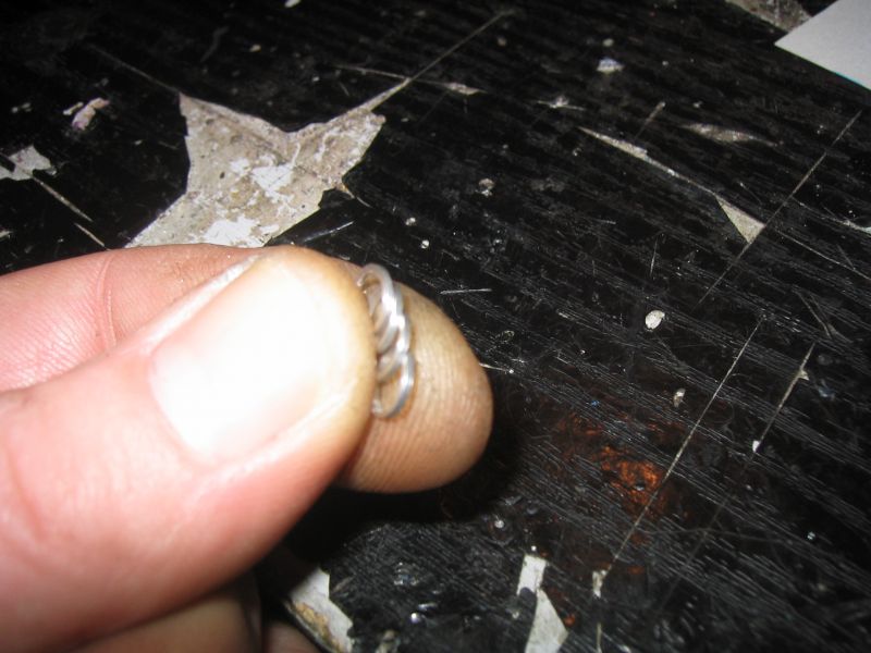
These were fitted to each of the stub axles, 1x between wheel-plate & bearing, 1x between circlip & bearing. They bear only on the inner races of the bearings, & adapt the shaft-length for use with these ballraces, by taking up any endfloat.
Custom F2
...
Hilux crossmember drawing
...
F2 axle drawing
...
Quattro radio lid
...
Holiday Buggy motor bracket drawing
...
Quattro resto
...
HitnMiss engine
...
Wild Willy resto
...
Mardave Cobra resto
...
Thunder Dragon resto
...
Grasshopper resto
...
XR311 resto
...
Modded XR311
...
Carbon 25th scratch build
|
|
|
Please Log in to join the conversation. |
Re: Project "Better XR311" 11 years 3 months ago #16651
|
As you've already seen, I was doing lots of bits all at the same time, so I'll come back to the gearbox now. I can't finish this bit of it yet cos Xmas has delayed bearing arrival (Spose that means I'll HAVE to fix the fence then...). This is what's done so far with the gearbox -
The main cross-shaft, output shaft, whatever you want to call it is prone to scoring damage & burring from grubscrews which have come loose allowing the various bits to spin on the shaft, on second-hand cars. This can make removal/fitting of the shaft difficult through bronze bearings, & impossible through ballraces. 1st job then was to run a file over any damage to remove burrs & swelling, so that the shaft will fit through the bearings & metal crown gear. The 2x bearings here are standard 1150s & the drive hexes already have "noses" machined onto them (So they bear only on the bearing inner races). This bit was easy, I just needed an inner race sized collar to go between the back of the metal crown gear & the bearing, which ended up being a replacement for the kit thrust washer that's usually fitted here (Don't appear to have a pic of it...) The other bearing that lives in the gearbox is a tiny flanged item (S2). The kit bronze thing that fits here is 4x6x2.5, with a 7x1 flange. The closest ballrace I could find to replace this is MF63ZZ, being 3x6x2.5 flanged. The bore is 3mm, there's no such thing as a 6 O/D ballrace with a 4mm bore, so I'll have to modify the shaft that fits in it. The flange size is also different to the bronze item. At the time, I was waiting for ballraces to arrive so I machined 3x up to allow me to put some bits together for measuring. This was to allow me to sort out something for a missing drive gear (At this point I was planning to use the original input shaft). Also needed a motor pinion. I had a dig about to see what gears I've got kicking about to vandalise. The input gear is 40 tooth, 0.6 module. SRBs use 0.6M, so I started looking there first... turns out the SRB final drive gear is 40T, so I grabbed a spare one of those. Also found a diff from a Bycmo Subaru, which is also 40T/0.6M. Took both to the shed to see what I could do. The required gear has a hex recess in one side, to locate with a hex integral with the input shaft. So does the SRB gear, so I decided to start with that (They're more readily available if I badword it up as well). Turns out the SRB hex is bigger than the XR311 one, but there would be enough depth to machine a 1mm deep XR311-sized hex in the SRB gear & pack out the gap with "instant metal". So, that was the plan for now. Couldn't find a 15T/0.6M pinion, but I did find a 14T/0.6M gear that used to belong in a battery drill gearbox. For some reason, this gear had the same O/D as what's listed for a 15T/0.6M, so I thought I'd try that first, just in case it might work. I'd also noticed that the input metal bevel gear had been brutalised, I guess in an attempt to get a stripped grubscrew out. Needed sorting so that came in the shed with me too. Bits I started with - 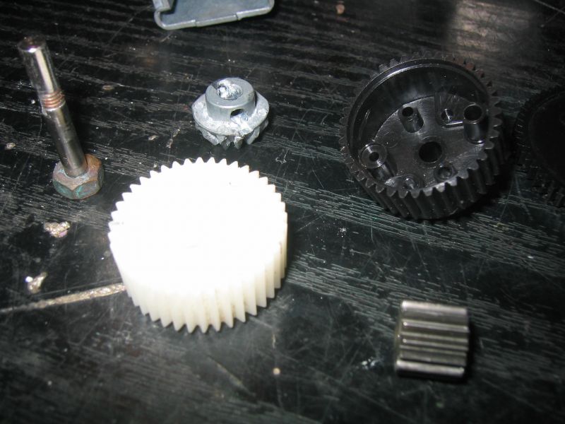
A couple of hours in the shed later, I had S2 bush replacements, the shorter C-hub squares (Mentioned earlier), shorter front suspension screws (Mentioned earlier), 4x M2.5 brass nuts to suit 4x M2.5 torx screws (Leftover Xbox 360 heatsink screws, for holding the Rx & battery plates on), a motor pinion & gearbox input gear 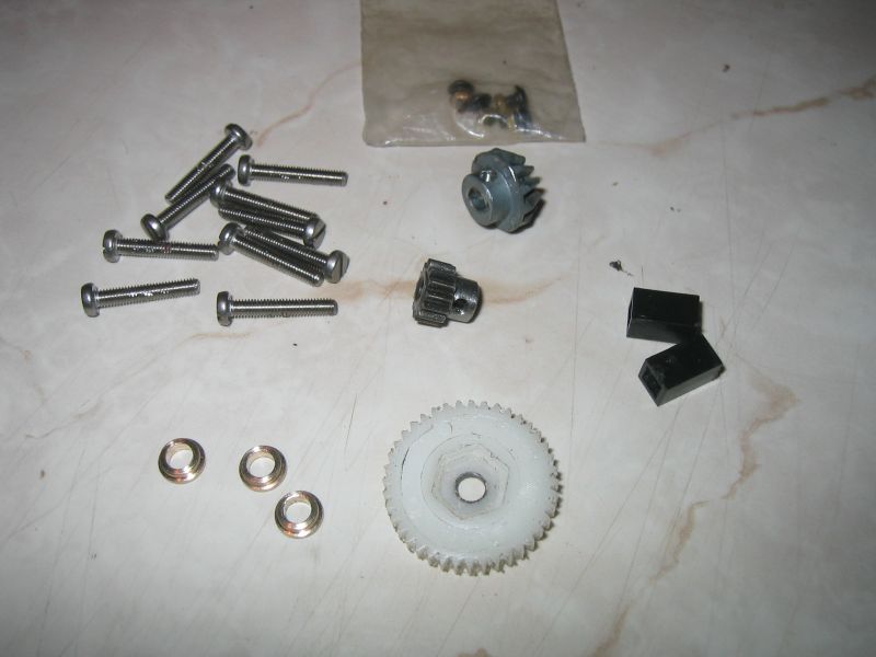
Fitted the input shaft to its new gear & filled the gaps with "instant metal". It was a lot of effort to avoid modifying the original input shaft, but I take the attitude that I won't modify vintage parts if there's any chance the original bits that fit with them could still be sourced, which in this case, they could, I just don't want to pay for them... In hindsight, I needn't have put so much effort into this, as the quest for suitable ballraces for this shaft highlighted the need to modify it, (Which I wasn't going to do) so I then decided I'd just be better off making another shaft that will suit the SRB gear & the ballraces. Anyway, fitted the bushes & gears for a quick feel/test. Yep, works, take it to bits again. Pic below shows the shortened front suspension screws, new pinion & drive gear (Before I had ballraces, or had sorted the steering, told you this wouldn't be in order!) 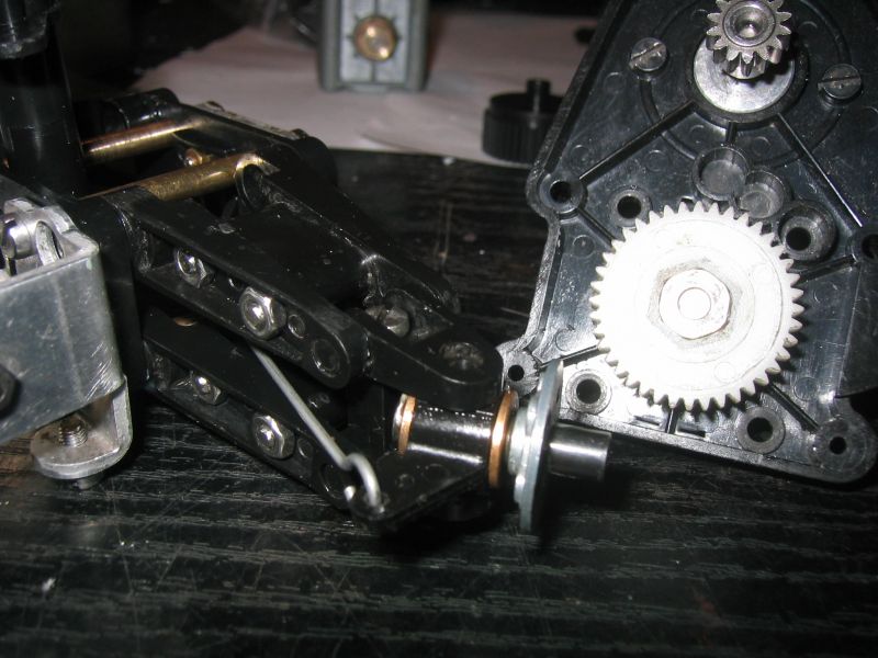
Ok, back to when I'd got bearings... Put my "S2" ballraces (MF63ZZ) into the outer gearbox & had a measure up - need to make a new shaft for the counter gear cos its shaft is 4mm & the bearing bores are 3mm. This will be 4mm silver steel with the ends machined down to 3mm to suit the bearings (Made a new one rather than modding the original). This is another position where the bronze bearings also act as thrust bearings, so I'll also need some inner race sized collar/spacer things here, 5 O/D x 4.02 I/D x 0.3mm thick... this'll be a laugh... Managed it, you can barely see the collars fitted on the new shaft! 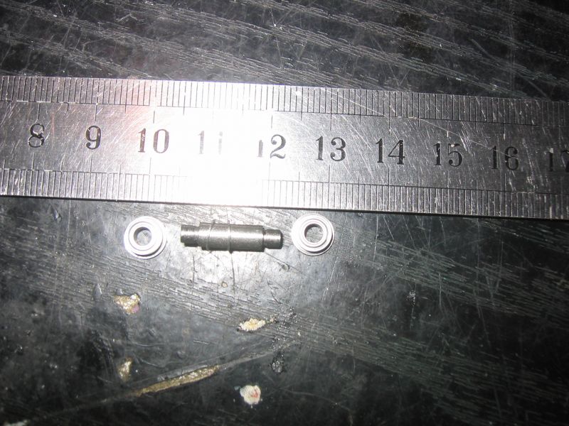
I had also previously copied some other bits from the other car for use on this one. In this next pic we have a drive cup for this car (Machined from uPVC), some modified M3 cheese head screws (Converted to 4-40UNC + home made nuts) for the other car, a pile of body clip slider thingies for both, & a pair of stainless chassis reinforcing plates (Rear suspension to chassis mounting bits) for this one 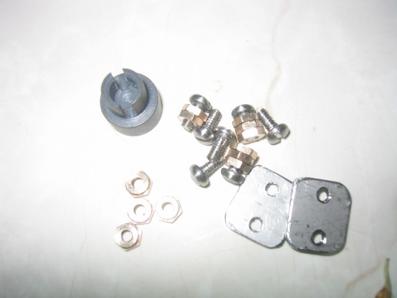
Custom F2
...
Hilux crossmember drawing
...
F2 axle drawing
...
Quattro radio lid
...
Holiday Buggy motor bracket drawing
...
Quattro resto
...
HitnMiss engine
...
Wild Willy resto
...
Mardave Cobra resto
...
Thunder Dragon resto
...
Grasshopper resto
...
XR311 resto
...
Modded XR311
...
Carbon 25th scratch build
|
|
|
Please Log in to join the conversation. |
Re: Project "Better XR311" 11 years 3 months ago #16653
|
Ok, a couple more bits just to tidy up what's left in the memory bank, to bring me up to date to how it is now, waiting for a pair of bearings before I can get on with assembling the rear end.
I was missing 2x complete rear wishbones, a pair of rear hubs & a gearbox cover, so again, using parts from the other car as patterns, I got stuck into a drop more moulding. 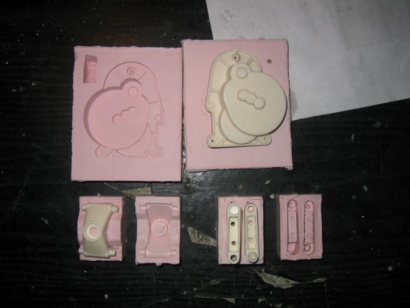
I had time, so these bits got post-cured to stop any possible stickiness/paint reaction problems. Then I cleaned them up, drilled out any blocked holes & made sure the bits all fitted together as they should, which they do. Then they were prepped & painted with Holts satin black automotive paint, which give a finish uncannily like the original parts 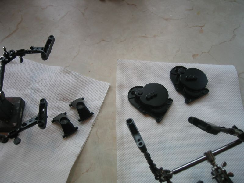
Very pleased with how these came out! The suspension bits have since been assembled & fitted with wheel bearings (4x 1150 ballraces). The rear axles had to be cleaned up with a file to remove burring etc caused by loose/slipping grubscrews, prior to fitting. There are collar/spacer things fitted to the wheel-plate side as per the original kit, but I didn't have these, so I machined some up using those from the other car to copy. Then I fitted the axles, drive hexes & cups to the suspension assemblies, which is kinda where we're at now. 
Next job will be to turn an M6 bolt into a special input shaft to fit my modified SRB drive gear & the new ballraces (When they turn up) - it needs a 10mm A/F hex & short 5mm shaft bit to suit the gear, 4mm shaft bit to go through the bulkhead bearings, a flat for the input bevel gear, & a 3mm shaft "nose" to engage with the "S2" ballrace in the gearbox. 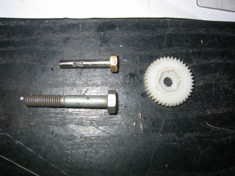
I can't really think of anything else I can sensibly get on with until the rear end's assembled, so that's going to be it for now
Custom F2
...
Hilux crossmember drawing
...
F2 axle drawing
...
Quattro radio lid
...
Holiday Buggy motor bracket drawing
...
Quattro resto
...
HitnMiss engine
...
Wild Willy resto
...
Mardave Cobra resto
...
Thunder Dragon resto
...
Grasshopper resto
...
XR311 resto
...
Modded XR311
...
Carbon 25th scratch build
|
|
|
Please Log in to join the conversation. |
Re: Project "Better XR311" 11 years 3 months ago #16656
|
Great build. If you need any more SRB gears, let me know. I've got millions of the buggers and nobody seems to want to pay decent money for them.
 |
|
Please Log in to join the conversation. |
Re: Project "Better XR311" 11 years 3 months ago #16683
|
Nice work again eddrick
")  I do like the torsion bars - but I do think you'll have just moved the problem to the wishbones, which are very weak around where the torsion bars fit  |
|
Please Log in to join the conversation. |

Re: Project "Better XR311" 11 years 3 months ago #16713
|
Cheers peeps!
Martin, I'm surprised there's no interest in those gears of yours, there must be loads of people with collected SRBs now, & what do they think they're going to do for gears once all the re-re ones have sold?! Mind you, if their cars are shelfers, there's no chance of ever wearing/breaking gears, maybe that's the cause? Jonny - yep, I know I've moved the problem, I was going to make up some thin-wall stainless reinforcing collars to go around the bits with the square sockets in them, but then had a head-wobble about drilling out the pivots to take them (That "don't want to vandalise vintage parts" thing). So far I haven't done anything that couldn't be reversed if someone wanted to return it to original spec. BUT, plan is to give it some hard once it's done, & see what breaks, I might do something with them then. I haven't seen any broken ones yet, but I'm wondering if it's to do with the plastic spigot wearing in the aluminium holes, or maybe there's too much clearance, allowing the plastic to swell & split? The last 2x bearings turned up xmas eve, so I was able to assemble the rear end. Gearbox is lovely & smooth now, well as smooth as an XR311 'box will ever be anyway! Haven't done much else with it though, due to xmas busy-ness. Did a bit today, started looking at bodies & wheels - gonna see how it goes before I post pics of it, just in case I have to abort
Custom F2
...
Hilux crossmember drawing
...
F2 axle drawing
...
Quattro radio lid
...
Holiday Buggy motor bracket drawing
...
Quattro resto
...
HitnMiss engine
...
Wild Willy resto
...
Mardave Cobra resto
...
Thunder Dragon resto
...
Grasshopper resto
...
XR311 resto
...
Modded XR311
...
Carbon 25th scratch build
|
|
|
Please Log in to join the conversation. |
Re: Project "Better XR311" 11 years 3 months ago #16865
|
Time for more progress pics I think!
Haven't got a huge amount done, but enough to talk about. Machined up a new input shaft to better suit the SRB gear & the undersize gearbox bearing 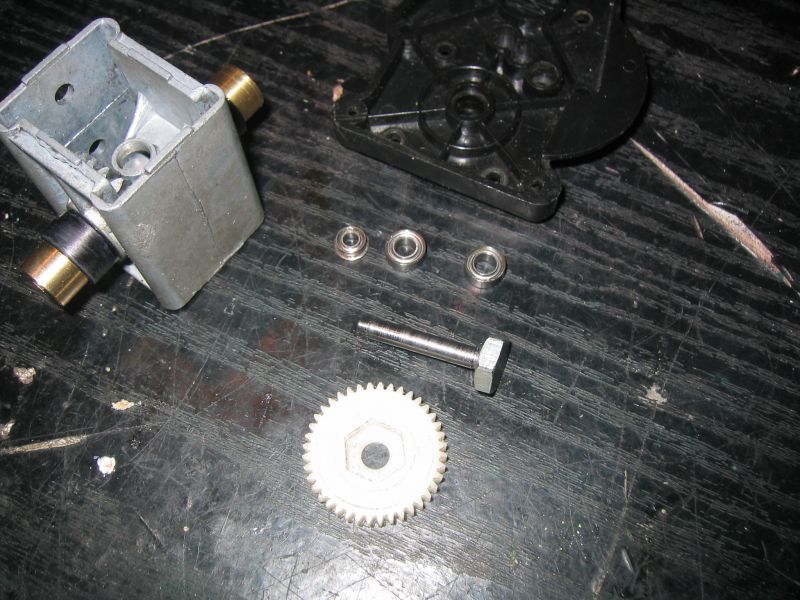
Put the back end together 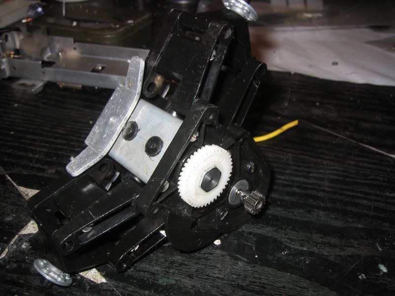
Mated the rear end to the rest of the part-built chassis & set up the torsion bars. They feel a bit stronger/harder than I would've liked, but I suppose I won't really know for sure until I get the rest of it together. If they turn out to be too hard, I'll just put some thinner gauge wire in them, because I can. 
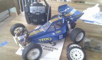
Time for wheels.... I've sort of settled on the body, it fits quite well size-wise, looks good & is held together with screws, which will make modifying it to fit the XR311 chassis easier. Unfortunately, it looks totally stupid with the XR311 wheels, so I decided I would adapt the "toy" ones to fit. Granted the "tyres" are only slightly "rubbery" (Possibly some form of PVC/vinyl), but this could work with the 2wd no-diff drivetrain to give me an awesome drifter, which suits me fine as I'm bored with waiting for an icy/snowy carpark now! Anyway, 1st task, pull my "toy" to bits, disassemble its wheel components & have a think on how to do this... 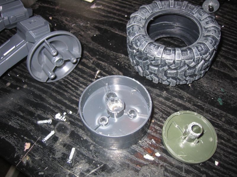
The "hubcaps" were glued to the centre-section, but didn't put up much of a fight - these will be screwed through the centre-section into my new adaptor plate. The new adaptor plate (Round fing on the left) was machined out of uPVC. It has the 5x holes for M2s to hold it to the XR311 hubs, plus another 3x holes to fix the centre-section to it, with self-tappers, as per how it originally was held together. Then, as I said, the hubcaps are screwed through to the adaptor. The tyres are clamped in place by the 3 bits 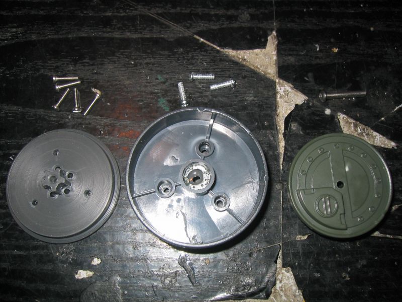
Custom F2
...
Hilux crossmember drawing
...
F2 axle drawing
...
Quattro radio lid
...
Holiday Buggy motor bracket drawing
...
Quattro resto
...
HitnMiss engine
...
Wild Willy resto
...
Mardave Cobra resto
...
Thunder Dragon resto
...
Grasshopper resto
...
XR311 resto
...
Modded XR311
...
Carbon 25th scratch build
|
|
|
Please Log in to join the conversation. |
Re: Project "Better XR311" 11 years 3 months ago #16867
|
Moving on to the body.
This has been time-consuming, with lots of taking to bits, cutting bits off, putting it back together to see how it fits, then taking it apart again, cutting more off, bending this, extending that, adding these & welding those. Sorry, I've been in such a flap trying to get it done before I run out of holiday, that I seem to have forgotton to take any progress/during pics... here's what I did, hopefully you won't find it too boring! Layed the body on the chassis to see what fouls what & where, marked with a pen what was going to be chopped out. Took it to bits to save inadvertent damage during surgery (Easy cos it's screwed together, not glued) Chopped out clearance for the gearbox/motor/rear end, removed lots of screw-pillars, so the body will sit over the various standy-uppy bits at the back. Reassembled some of it, then again laid it on the chassis to see what was fouling at the front. Marked those bits for chopping (Steering servo, linkage & servo-saver clearance), then took it to bits again for more surgery. After that hacking session, I again re-assembled it, laid it on the chassis & looked at the middle - the interior footwells were fouling the chassis as they were, let alone clearing the space intended for the battery pack. So, more marking & take it to bits again! Fortunately, the interior is removable as a "lump", so the next lot of modifying could be done without messing about with the rest of the car. Unfortunately, making the footwells clear the chassis (& battery) meant making them smaller, which would cause me a headache fitting the XR311 driver (He fitted quite well before modding). The footwells were cut open to give me the clearance I was after, then boxed in again with some shaped leftovers from previous hacking. These were welded in with the old soldering iron trick, & look the part. I used a similar trick to add some outriggers at the front, to take the XR311 front body mounts, so the slider thingy could be used to good effect. Chopped out clearance for the Rx & ESC (Yep, decided to go ESC for this one, rather than risk frying an original XR311 MSC). In its original condition, the "toy" body had a rotating gun turret at the back. The XR311 rear body mount/rollbar sticks through the body, proud of any flat mounting surfaces, so I decided to extend the rotating turret height-wise & re-use that, after all, that hole is where it belonged.... Now, this piece is rigidly fixed in, stands slightly proud of the deck & is the perfect place for mounting the rear body securing bobbin thingies, so I can also stick with the original rear mounting method too. Hopefully all that wordstuff will help prepare some understanding about what the next 3 pics are about... Chassis/gearbox clearance 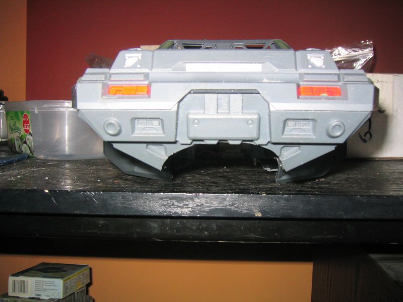
Modified footwells 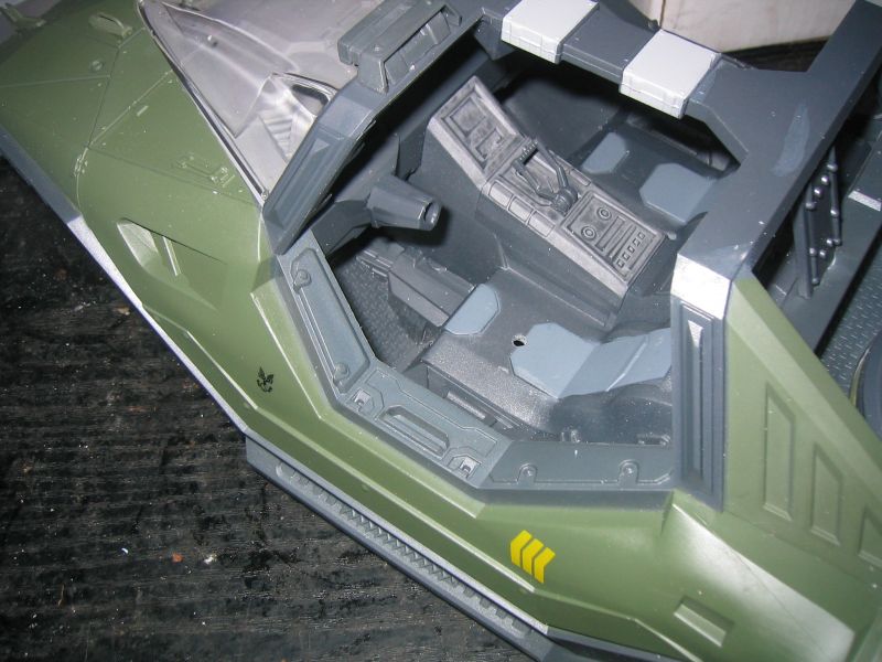
Underside, showing cutout for steering gear at front, footwell welding/additions, turret mods & rear mounts, outriggers for front mounts, cutouts for Rx/ESC 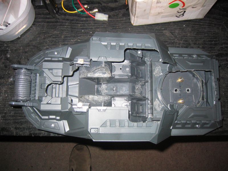
Next jobs are to make my XR311 bloke fit (Already done this), make an aerial tube holder, & possibly re-make the front bumper bracket (Think I want a shorter, more off-roady-looking one)
Custom F2
...
Hilux crossmember drawing
...
F2 axle drawing
...
Quattro radio lid
...
Holiday Buggy motor bracket drawing
...
Quattro resto
...
HitnMiss engine
...
Wild Willy resto
...
Mardave Cobra resto
...
Thunder Dragon resto
...
Grasshopper resto
...
XR311 resto
...
Modded XR311
...
Carbon 25th scratch build
|
|
|
Please Log in to join the conversation. |
|
|
|
Time to create page: 0.283 seconds