TOPIC:
Blakbird's 58391 Hotshot Build 4 years 9 months ago #55843
|
Tamiya had pioneered the RC buggy in 1979 with the 58015 Rough Rider, but everything was rear wheel drive until 1985 and the release of the 58047 Hotshot. It is hard to overemphasize how much changed in that time. The SRB chassis used mostly metal and had simple swing arm suspension with a locked, solid rear axle. The Hotshot came along with four wheel independent double wishbone suspension, a plastic chassis, large bore oil filled shocks, and most importantly, four wheel drive. Building this now, it does not feel like a design which is 30 years old. Many of the basic design details are still in use today.
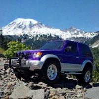
The most obvious new feature of the Hotshot is 4WD. The motor still sits near the back, but ahead of the rear axle. Power is transferred to the front axle with a propeller shaft (or drive shaft). There are open geared differentials both front and rear, but no center diff. The front wheels share a single lateral shock absorber while the rear wheels use the iconic shock mounted under the wing and driven by a fairly complex linkage. The standard 6-cell battery pack is slung under the chassis just ahead of the rear wheels. Much of the caged chassis is left exposed by the minimalist body so you can still see all the good bits. The Hotshot reminds me of a bikini. The Hotshot lineage persisted for a long time. The upgraded 58054 Supershot came out in 1986 followed by the 58062 Hotshot II in 1987. The original Hotshot was re-released in 2007 as set 58391 which is the version I was able to acquire. There was also a 1/12 scale version in the GB-03 Tamtech Gear line released as 56711 the same year. A number of other models used the same chassis or a derivative thereof. The Hotshot drives amazingly well for the first of its breed. It is stable, well planted, has good traction, and even jumps well. In fact, I can't really think of a performance complaint. It is not as nimble as a modern racing buggy, but does very well nonetheless. The only change I made was to swap out the stock motor for the recommended Dirt Tuned version. The re-released Hotshot comes in a lovely box with vintage artwork. Unlike the original there are no blister packs inside, but the contents are nicely divided and there is an inner box on the right for all the hardware. 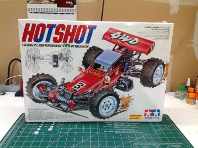

Unpacking the box shows you that this is a pretty serious model. There are a very large number of plastic parts trees here along with 4 labelled hardware bags and several other bags of metal bits and bobs. The only immediate disappointment is the use of plastic bushings, but I've taken care of that with a set of ball bearings from the start. 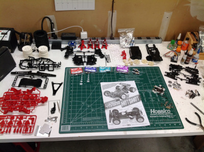
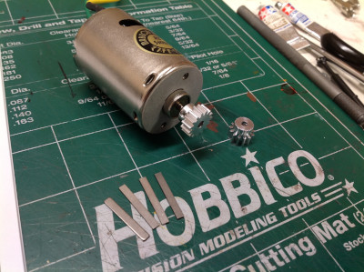
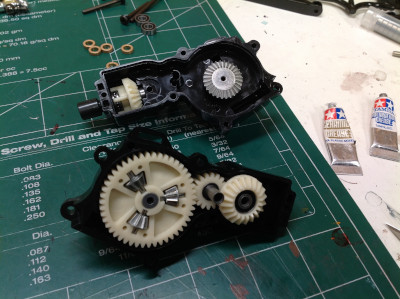
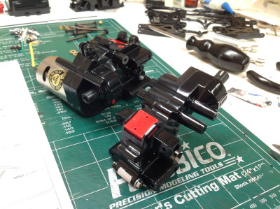
The build begins with the rear differential and gearbox assembly. The spider gears are housed inside the ring gear making for a very compact design. The drive gear you see on the far left is 3 gears in one. The large spur gear mates with the motor pinion, the bevel gear transfers power to the prop shaft and off to the front wheels, and the smaller spur gear (seen hiding through the holes) drives the rear differential. On the right you can see the mating bevel gear for the prop shaft. Note the thrust bearing behind the gear. Bevel gears always generate thrust loads, but as far as I know the Hotshot chassis is the only one to offer a thrust bearing to resist them. The original Hotshot required you to build up the thrust bearing from parts, but the re-release uses a pre-assembled unit locked by a swage ring. 

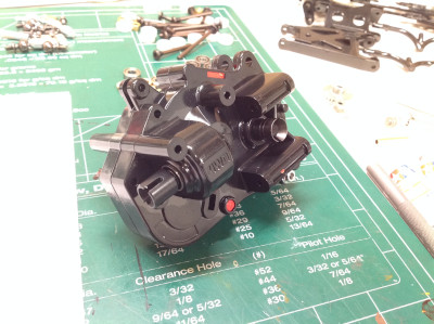
Now the gears can be installed into the gearbox. The bevel gears for the differential are supported by a thin central axle. On the original, the drive cups were held with fiddly little C-rings, but on the re-re they use simpler E-clips. The right hand image shows the rear gearbox all buttoned up. 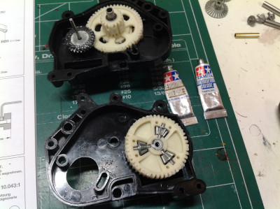
|
|
|
Please Log in to join the conversation. |
Blakbird's 58391 Hotshot Build 4 years 9 months ago #55844
|
The kit comes with both a 13 tooth and a 15 tooth aluminum pinion gear, but the model supports optional 16 or 17 tooth gears for even higher speed. I used the 15 tooth gear. This chassis uses an interesting method of adjusting the gear mesh. There are a set of 4 plates or shims which can be seen in the right hand image on either side of the long screw which supports the motor. The 15 tooth gear is spaced by using 2 on either side of the screw. Other pinion sizes set the mesh by putting the plates in different positions.

The front gearbox is next and is built much like the rear. It uses the same differential and bevel gear with thrust bearing. 
The final front gearbox is quite slim and compact. The outer profile of the housing is quite complex because it will form the basis of the front suspension attachments and provide the structural support to the main chassis. The right hand image shows the finished front and rear gearboxes which, while almost the same on the inside, look completely different on the outside. 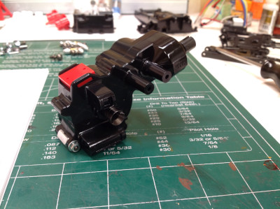
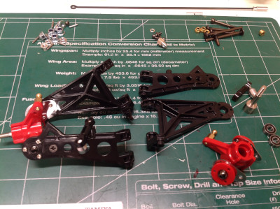
Now we'll start work on the rear suspension. The lower arms are wishbone style and the upright hubs are molded in bright red. In the right hand image you can see that the upper arm is much shorter than the lower which will result in camber change as the suspension compresses. 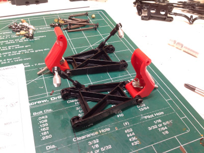
|
|
|
Please Log in to join the conversation. |
Blakbird's 58391 Hotshot Build 4 years 9 months ago #55845
|
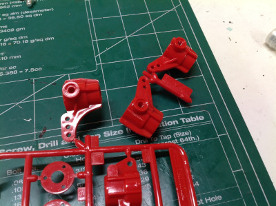
The front suspension is next. The original steering knuckle (D1 and D9, still present on the parts tree) has been replaced with a new part as shown. From a careful comparison, it appears that the critical geometry is exactly the same. Although the steering arm portion is shaped differently, the relationship of the kingpins to the outer ball joint hole is the same and the bearing offset is the same as well. It appears then that the only change is that the new parts have the kingpin threads molded in and the old part does not. The way the kingpin attaches to the suspension arms is fascinating. The end of each kingpin is a large ball which is trapped by a pair of parts, a red plate and the end of the suspension arm. This pair forms the seat for the ball joint. A metal plate adds strength to secure the whole thing to the suspension arm. Look closely at the right hand image to see the details. The Hotshot family is the only chassis to use this design.
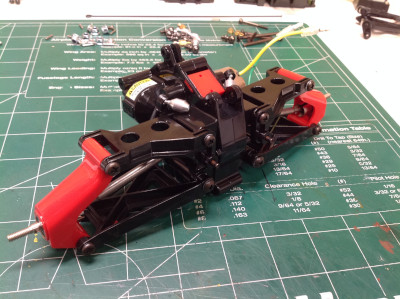
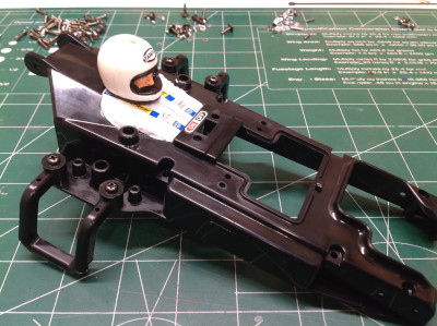
The completed front gearbox and suspension module is shown at left. Note the unconnected ball ends for a sway bar which has not yet been attached. The next thing to build and paint is the main chassis tub. This is unusual for several reasons. Firstly, the tub is inverted. In most cases a bathtub chassis is concave and the opening faces up. In this case the tub is convex and faces down. The driver figure is integral to the chassis tub. In the original model, this part had a solid top and no access to the electronics beneath without a significant disassembly. This design persisted through the Supershot, but the Hotshot II added an access cutout (shown at right) which is used for this re-release. This cutout is nice for access but greatly reduces the torsional and bending strength of the middle of the chassis. 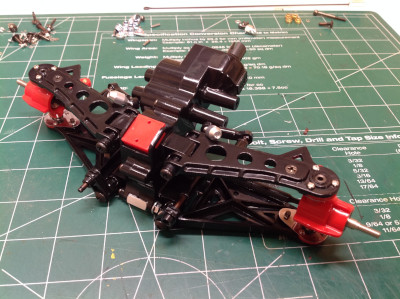
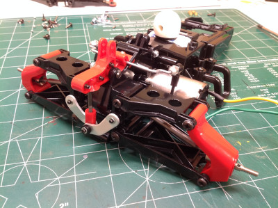
The highlight of this model, in my opinion, is the rear suspension system. I always knew that the single rear shock was mounted longitudinally above the rear gearbox, but I could never quite tell how the vertical motion of the rear arms made it around the corner and up to those shocks. Hopefully these photos will help. On the left is the main crank system which is the key to the whole thing. It is shown attached on the right. Each upper suspension arm has a built-in control horn which attaches to one end of the aluminum links as shown. As the upper arm rotates, the aluminum link pushes both inward and vertically. The inward force is cancelled out by the link on the other side, but the upward force is transferred to the red crank which pivots on the top of the gearbox. The other end of the red crank will attach to the shock later. There's also an anti-sway bar which is secured to the top of the gearbox and the lower arm as shown. Interestingly, it serves to counteract the tendencies of a shared rear suspension. With a shared shock, upward movement of one side tends to push the other side down. However, upward movement of the arm tends to lift the other side through the sway bar. With both of them in combination it partially cancels out and works more like an independent suspension. 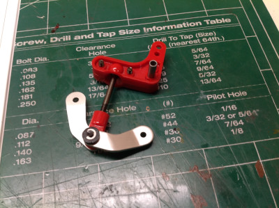
Now the front gearbox can be attached to the main chassis tub. Notice the FRP forks which are used as pivot supports for the front sway bar. The right hand image shows both front and rear gearboxes from beneath so you can also see the prop shaft (a Tamiya first at this point) running right down the length but not quite centered. The original model used a prop shaft with crowned hex drives on the ends which was subject to rapid wear, but the re-re uses a more standard dog bone style shaft and mating drive cups. You can also see that at this point the chassis is pretty weak. Because of the large cutout in the middle of the tub, there is very little material connecting the front and the back halves right now. 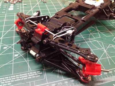
|
|
|
Please Log in to join the conversation. |
Blakbird's 58391 Hotshot Build 4 years 9 months ago #55846
|
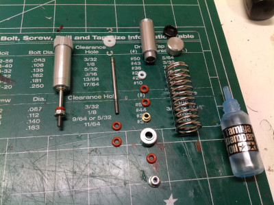
The shocks are a thing of beauty and are built in two stages: a metal stage and a plastic stage. You can see the metal parts including the shock body, the caps, the rod and the spring. There are a lot of O-rings here used as both seals and spacers. The 2-hole piston head is Delrin and a bladder is used for volume compensation. There are no connectors at either end of the shock. Although it looks much like the original, the shock from the original Hotshot is quite different. It uses an internal floating piston for volume compensation and the o-rings are permanently swaged into the end and cannot be removed. The new design is simpler and easier to repair.
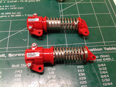
The second stage entombs the metal shock in a plastic housing. The right hand end is an offset rod end. The offset is important. A normal shock is a two-force member which means that the loads at either end can only run down the center and therefore the shock can only be in tension or compression. Because the rod end support is offset, this shock is also in bending which puts a lot more stress on the rod. On the head end is a rotating collar system which allows for three different preload settings just by turning the collar and locking into one of the three sets of grooves. In the right hand image I show the shock adjusted to the two extreme preload positions. 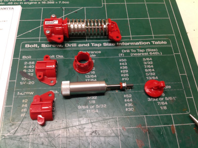
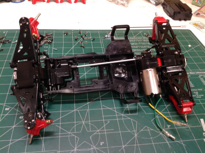
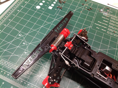
Here the shock absorbers have been installed in both the front and rear. The front uses a single damper like the rear, but with a much simpler lateral attachment directly to the lower suspension arms. The bumper can then be installed to protect that otherwise protruding front shock from damage. 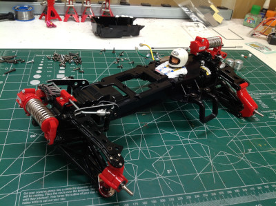
The electronics are all contained in a box which hangs under the front of the chassis tub. In the modern version this contains the steering servo (with integrated servo saver), electronic speed controller, and receiver. In the original version things were much more tight. An additional servo for the mechanical speed controller was needed behind the steering servo which required the receiver to be placed on top. There was never any room for a receiver battery so the original included a tiny BEC located on a chip with the on-off switch. Once installed, you can see how the opening in the tub allows access to the electronics although this is much less needed with modern radio equipment not requiring a crystal. 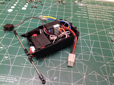

|
|
|
Please Log in to join the conversation. |
Blakbird's 58391 Hotshot Build 4 years 9 months ago #55847
|
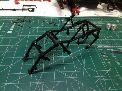
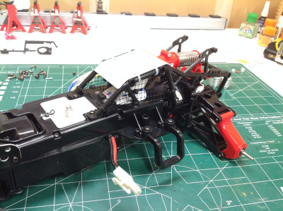
This lovely plastic cage does more than just look good; it helps to strengthen the center of the body where the cutout for the battery is. The model includes nets in place of side windows and a nice formed sheet metal part for a roof which attaches with cable ties. A couple of hooks on the cage serve as the pivot axis for the rear sway bar.
Here's a view of the battery installation as seen from the bottom. The battery hatch is an FRP fork which hinges at the back. This plate actually serves as an important structural stiffener for the chassis. The original model included the iconic cylindrical heat sinks for the resistors which are no longer needed on the re-re, but Tamiya included them anyway just for the appearance. I'm glad they did. 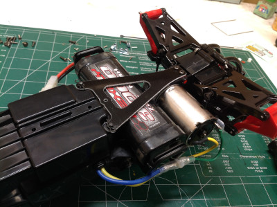

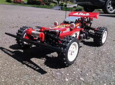
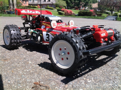
The wheels do not connect to the axles with standard 12mm hexes, instead they use a triangular drive with 3 pins. This means you are very limited in the wheels you can use unless you want to retrofit standard hexes. I like the look of the stock wheels. The tires use a fascinating combination of conical and elliptical pins. This completes the rolling chassis and the model can be driven at this point. In fact, in some ways the model looks best in this state of trim. 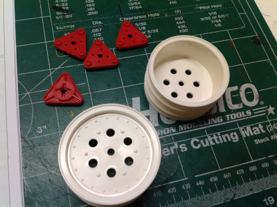

|
|
|
Please Log in to join the conversation. |
Blakbird's 58391 Hotshot Build 4 years 9 months ago #55848
|
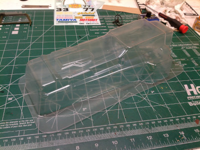
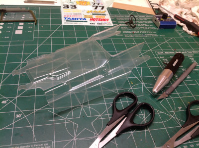
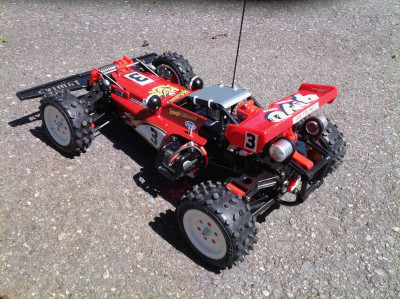
Time to work on the body. It starts as a molded polycarbonate shell as shown which must then be trimmed. Sadly, I cut the body by following the lines but without referencing the instructions and ended up cutting out the humped section over the "engine" in error. I had to throw away the body and order another. I'm glad this wasn't an original vintage body that I destroyed so foolishly. The right hand image shows the correctly trimmed body. This is tough one to trim with the narrow slots for the front sway bar supports and the very visible section surrounding the driver which must be just right.
I decided to kick it up a notch and use Mica Red instead of plain Red paint. This extra metallic sparkle looks good, but then I continued my trend of screwing up the body by backing it in black (which I always do) before first backing it in silver. This resulted in a darkening of the red which looks fine except that it doesn't match the spoiler which I didn't back at all. Still, the final model looks really good with the decals installed. It is hard to believe the first 4WD model could be so refined right out of the gate. 
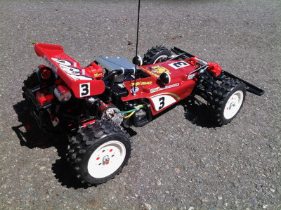
As a final curiosity about this model, it comes with a wire loop that can be inserted into the front of the electronics box which, when used in combination with on open battery door, serves as a stand for easy maintenance. I haven't seen this in another model before. 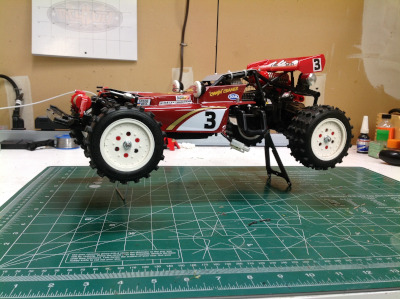
|
|
|
Please Log in to join the conversation. |
Blakbird's 58391 Hotshot Build 4 years 9 months ago #55849
|
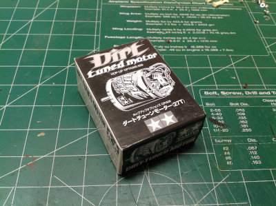
This model doesn't need much in the way of upgrades since it performs so well out of the box, but I was intrigued by the idea of the optional Dirt Tuned motor which I'd never tried. This is a 27 turn motor just like the stock silver can so it is not really any faster, but it does have replaceable brushes and don't forget that it looks cool.
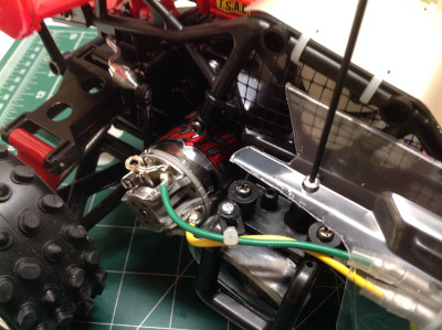
These pictures show the motor installation before and after the upgrade. The visual difference is subtle but you can certainly discern the higher quality motor on the right. 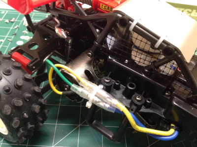
|
|
|
Please Log in to join the conversation. |
Blakbird's 58391 Hotshot Build 4 years 9 months ago #55850
|
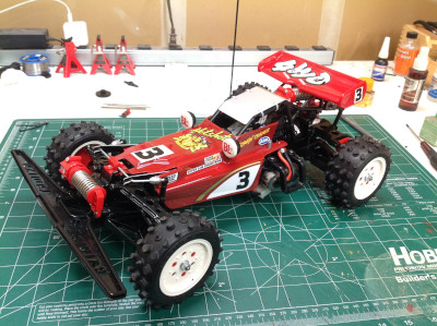
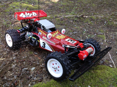
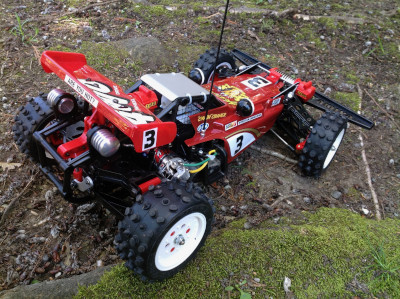
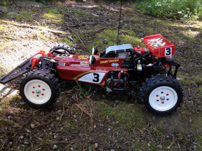
Considering this was the first 4WD buggy they ever made, Tamiya really knocked it out of the park in the looks department. This might be the best looking buggy of all of them in my humble opinion. I love the color, I love the tires, I love the minimal body that shows off the chassis, I love the cage that shows the driver, I love the side curtains, and most of all I love the suspension. I even think the antenna looks good so I used it even though it is no longer required.

The following user(s) Liked this: stingray-63, EOL
|
|
|
Please Log in to join the conversation. |
Time to create page: 0.241 seconds