|
|
|
TOPIC:
Blakbird's 58268 Mammoth Dump Truck Build 4 years 9 months ago #55911
|
I've been searching for the Mammoth Dump Truck forever. Let's build it!
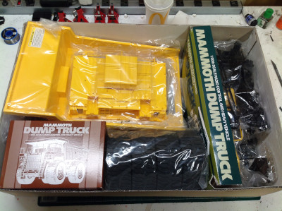
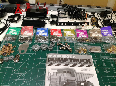
As you might expect, the Mammoth dump truck comes in a box of truly legendary size. The majority of it is filled with the single piece bed with another substantial portion being occupied by the huge (and unique to this kit) tires. The hardware box, though not all that big, weighs a whole lot because of how much steel and aluminum is inside. 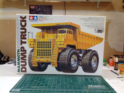
Although the body might be quite simple and only composed of a handful of parts, not so for the chassis. Here are the huge number of parts trees which make up the parts for the chassis assembly. Note the 8 colored hardware bags. These are not sorted sequentially so you need to open all of them at once and pick through them to find the parts for each step. Also note the huge pile of metal bushings. I replaced all of them with ball bearings. 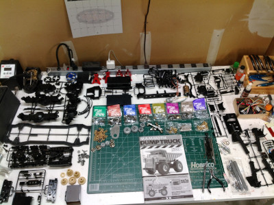

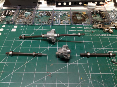
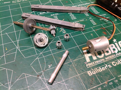
Here are some close-up images of the parts. I was really surprised (and pleased) by how complex this model turned out to be. Makes me feel a little less terrible about the small fortune it cost. 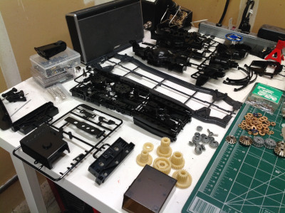
These images show the main gears. Note the very large pitch of the gear teeth. They are actually not all the same pitch. The tooth size gets bigger as you get further from the motor, since the reduction makes the torque much higher at those stages. By the time we get down to the axles the teeth are truly huge. Within the main gearbox shown here there are 2 stages of reduction. 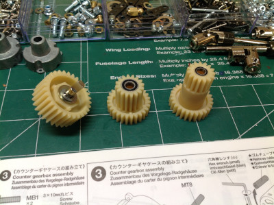
|
|
|
Please Log in to join the conversation. |
Blakbird's 58268 Mammoth Dump Truck Build 4 years 9 months ago #55912
|
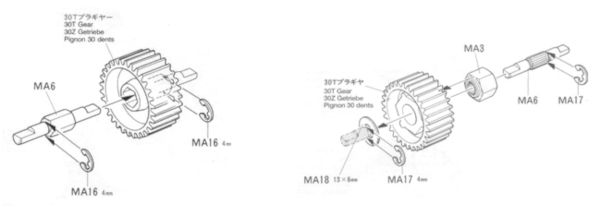
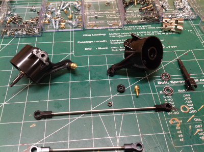
This is a good time to take a diversion into the history of the Juggernaut chassis. The original Juggernaut was a disaster due to a weakness in the gearbox that caused it to destroy itself almost immediately. This was corrected with repair kits and then later in the Juggernaut 2 on which the Mammoth is based. The below picture shows the only difference between the original Juggernaut and the Juggernaut 2. On the left you can see the small hex on the axle which drives the main transmission output gear. The hex slot in the nylon gear would strip allowing the gear to spin freely on the axle. On the right from the Juggernaut 2, Tamiya has instead splined the shaft and slid a metal collar over that with a much larger hex to spread out the load. It is odd that Tamiya made this error considering that the original Juggernaut came out in 1999, but years earlier the configuration on the right (the one that works) was already used in the King Hauler transmission. Perhaps tractor trucks are developed by a different team who was then called in to consult on this problem.
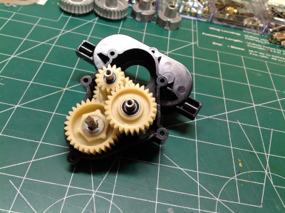
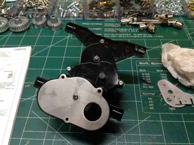
Back to the build. On the left you can see what looks like a human heart but is actually the reverse side of the gearbox that we built earlier. On the right you can see another housing which supports the motor. Note that the Juggernaut uses dual motors but the Mammoth uses only one, instead adding another stage of gear reduction to provide more torque and less speed. 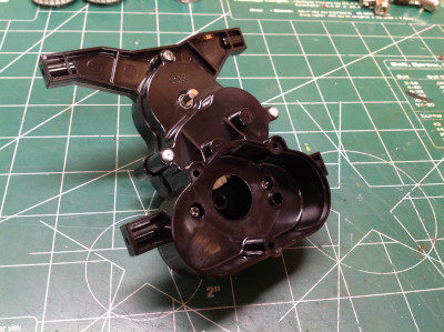
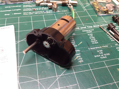
Time for another diversion to explore the extra gear stage that the Mammoth adds compared to the Juggernaut. On the left you can see the dual motor installation of the Juggernaut. The two motors share a common spur gear which then plugs into the existing gearbox. On the right you can see the Mammoth. The spur gear from the Juggernaut is retained (hidden) but is now driven by another gear between it and the single motor. This extra stage contributes an additional 2.7:1 reduction so the Mammoth is a lot slower than the Juggernaut. This change also moves the motor position to the center. 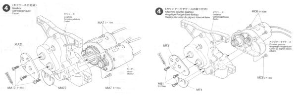
Here you can see a better view of that additional gear stage. The gear on the far left would be the spur for the Juggernaut. The gear shown to the right of that is now the main spur. The metal plate shown on the far right would have supported the motors on the Juggernaut, but instead has a hole for the additional gear. 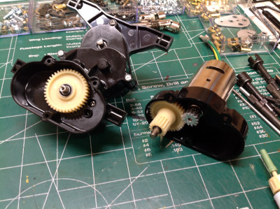
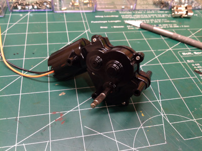
Here's the completed gearbox. The motor is hidden in the back but you can see the wires. Barely visible on the bottom is one of the transfer case output shafts with a flat on it for the drive shaft set screw. There's another on the other side connected directly to it. The front and back shafts spin together; there is no center differential. Let's do some simple math to find the overall reduction of this model.
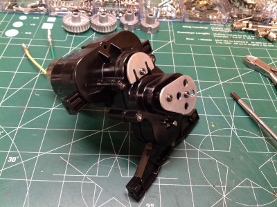
So assuming about 12,000 rpm at the motor under reasonable load, that's 131 rpm at the wheels which is about 2 revolutions per second. That's not very fast. However, considering what this model can weigh with a load of rocks and the fact that it needs to be able to haul that load over rough terrain, we're going to need that torque. It's easy to disparage cheap silver can motors, but it is also amazing how much work you can get out of them when they are used correctly. |
|
|
Please Log in to join the conversation. |
Blakbird's 58268 Mammoth Dump Truck Build 4 years 9 months ago #55913
|
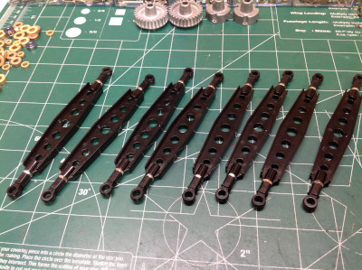
Time to start work on the axles and suspension. The build begins with 8 identical suspension links. You'll want good callouses on your fingers before you start these. On the right you can see the upper and lower housings of one of the axles, each with two links attached.
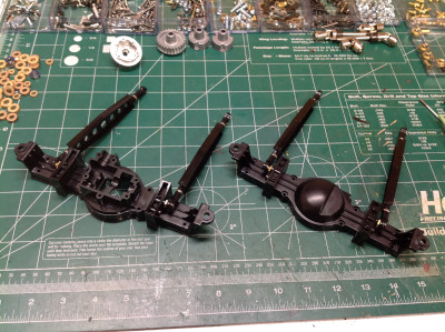
This is a serious axle which contains its own set of bevel gear reduction in addition to the differential. You can see the sizable metal bevel gears on the left which are sadly supported by some tiny bearings. You can see how these fit into the top of the axle housing on the right. Front and rear axles are identical, so one is shown with the cover removed and the other all buttoned up. This identical axle was later carried forward into the TXT-1 and is still in production in the TXT-2. 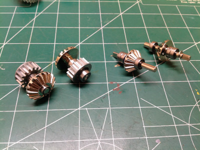
The differentials aren't messing around. They are all metal and they are large. The diff shown on the far left is completed while the one just right of it is opened up so you can see the spider gears inside. Note that the ring gear uses spur teeth rather than bevel teeth. I was more concerned with wear than with efficiency on this model, so I ended up packing these diffs heavily with grease. On the right you can see how the axle shafts plug into the differential housing and connect with splines at the end. 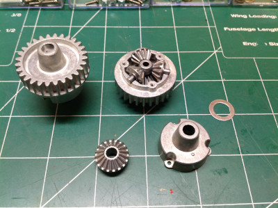
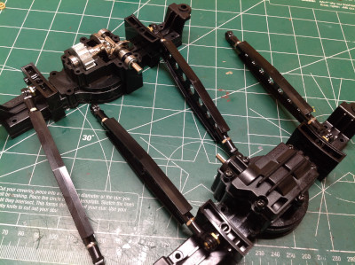
Now we can see a completed axle next to one with the cover removed revealing the differential assembly. On the right you can see one completely closed up with the steel telescoping drive shaft attached. This axle is huge. Other than the size, one unusual feature is that the "pumpkin" faces down rather than back. On a side note, I found it interesting that the gear cover on the right is prominently stamped with the year "2000". The Juggernaut came out in 1999. I would be willing to bet that they added this to the mold just to remind everyone that this is now the Juggernaut 2 and not the original. It didn't work. The Juggernaut chassis died a reputation death. 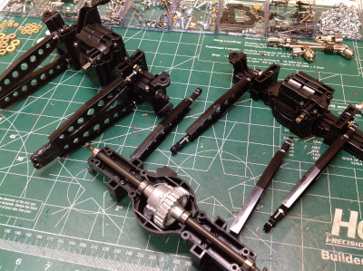

|
|
|
Please Log in to join the conversation. |
Blakbird's 58268 Mammoth Dump Truck Build 4 years 9 months ago #55914
|
It's pretty strange for a truck to have both a 4-link suspension and leaf springs, but that's what we've got here. Each leaf stack has 4 leaves of steel and is seriously stiff. They attach to the axles with the crazy long U-bolts shown on the right.

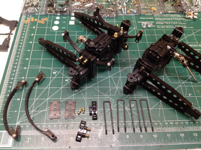
Turning tires of this size is going to take a pretty stiff crank. There is a servo saver with adjustable spring inside this crank, but it has almost no give in it. Just enough to ease an impact a bit. On the right you can see the enormous steering knuckles. Note that these parts are copied directly from the original Clod Buster. In fact, they still have the words "Clod Buster" molded right into them. 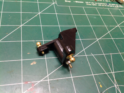
The Juggernaut uses 4 wheel steering so both front and rear axles are totally identical. However, the Mammoth only has steering in the front so the rear axle (shown on the right) has no steering crank or tie rods. Instead it uses plastic part K1 to lock the knuckles perpendicular to the axle. This part was never used in another model so I hope I never break it. 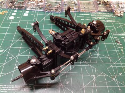
Here are the completed front and rear axles with metal bumpers attached. This model uses a chassis mounted steering servo so we haven't gotten to any electronics yet. 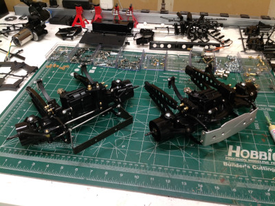
The following user(s) Liked this: Jonny Retro
|
|
|
Please Log in to join the conversation. |
Blakbird's 58268 Mammoth Dump Truck Build 4 years 8 months ago #55976
|
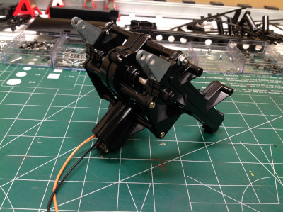
The lift actuator needs to be built before we get started on the chassis because it sits between the chassis rails. As you can see, all the gears for the lift system are metal. The motor is 370 sized with a worm gear attached. You can see that the gear second from the left has a lobed driver which can theoretically act as a clutch if too much torque is applied, but I've never slipped it.
Here is the arrangement of gears inside the gearbox. The motor will insert from the right. The protruding shaft is output. There are 3 total stages of reduction. The number of teeth per gear is not listed in the instructions and there are no plan views of gears B and D to count so I can't calculate the total reduction, but it is considerable. There are metal bushings here, but I thought they were adequate for this application so did not replace them with ball bearings. The completed gearbox is shown on the right. 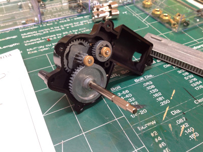
The lift actuator uses a dual rack and pinion system. The output shaft of the gearbox will drive the small pinions shown which translate the metal lift racks. This layout is only possible because the Mammoth is so tall. When retracted, these racks hang far below the chassis. 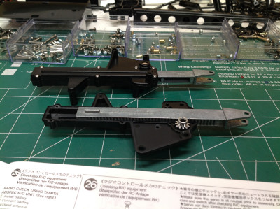
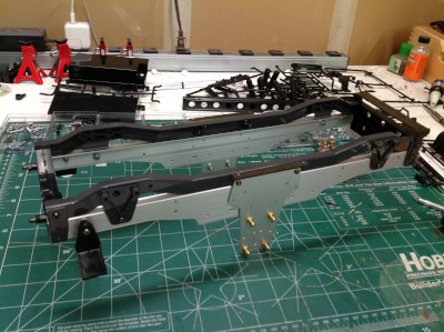
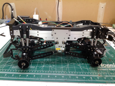
The chassis is built using a TVP (Twin Vertical Plate) support system. The black chassis rails shown on the right are plastic, but the huge supports under then are aluminum. The long vertical aluminum plates are supports for the suspension links. You can see "4x4x4" etched into the plates from the Juggernaut, but it is not correct for the Mammoth since we don't have rear steering here. 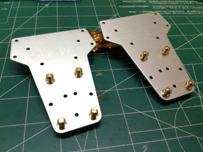

|
|
|
Please Log in to join the conversation. |
Blakbird's 58268 Mammoth Dump Truck Build 4 years 8 months ago #55977
|
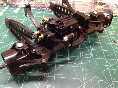
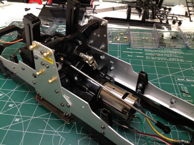
We can now connect the left and right chassis rails with a front and rear plastic cross member. The majority of the lateral strength actually comes from the lift actuator and the gearbox though. On the right you can see the lift actuator installed between the chassis rails, and you can see how far down the rack gears protrude. The slot in the rear cross member is where the battery will go.
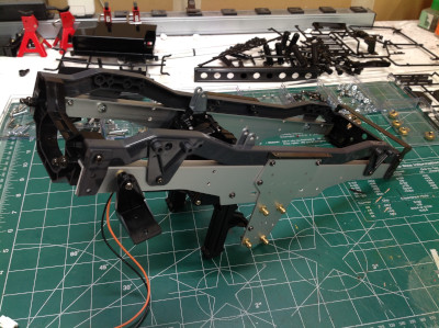
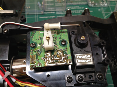
The steering servo is chassis mounted and faces down as shown. I chose a Futaba metal gear servo with a torque of about 125 in-oz. This is not a huge torque compared with a crawler servo, but I'm not going to be doing heavy off roading with this vehicle. Note the metal bracket which helps support the servo output horn. On the right you can see how the gearbox rigidly ties the left and right chassis rails together. 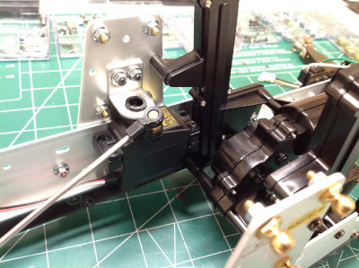
We can finally install those huge axles to the chassis using the 8 identical links we made earlier. Installation consists simply of popping on the 16 ball joints and attaching the drive shafts. 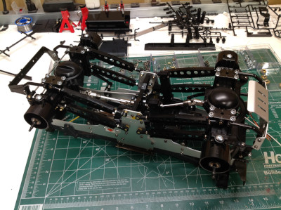
This model uses 8 shocks. These are friction dampers with no oil, and in fact they don't really have any friction either. As it turns out, the suspension is so stiff that it barely moves so the level of damping is irrelevant. At least they look pretty good. Golden oil dampers were available as a hopup, but are worth their weight in real gold now so I don't have any. 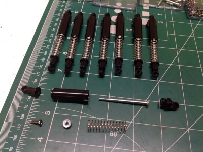
|
|
|
Please Log in to join the conversation. |
Blakbird's 58268 Mammoth Dump Truck Build 4 years 8 months ago #55978
|
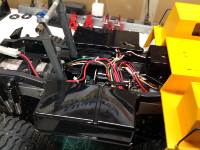
Wiring a 2-channel RC is usually a pretty trivial matter, but not so here. We have servos for both steering and throttle because of the Mechatronic Speed Control. The MSC uses a servo for input, but it is not mechanical. It has an actual FET and proportional control with a built-in BEC and no external resistor. This means the battery power has to pass through the MSC before going to the radio and to the main motor. But that's not all, we also have the Plus 1ch Control Unit which drives the lift actuator without an additional channel. This unit is commanded by holding full left or right steering for more than 1 second, but only when stopped (no throttle). It therefore needs power input, power output, and pass-through for both radio channels. It also uses a pair of limit switches to shut off the lift actuator at full up and full down to prevent stalling the lift motor. Add all of this together, and you get the huge mess of wires shown. I had originally planned to replace the whole system with a modern ESC and put the lift actuator on a 3rd channel, but the system works well and is part of the charm of this historic model so I have left it stock.
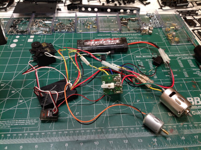
The model includes a good system for routing and restraining the wires and making them reasonably neat. This is pretty important because there are some big moving parts in back that could destroy the wiring if it was not carefully protected. The modern receiver on the far left looks out of place for being so tiny. The Mechatronic Speed Control shown on the right is a convoluted idea if ever there was one. First we use a potentiometer on the transmitter to convert a rotation to a signal. Then we sent that signal to a receiver which outputs to a throttle servo. That throttle servo uses another pot to detect its own output position. Then, finally, the MSC takes the servo output through another pot to command motor output. A modern system eliminates two of these steps. 
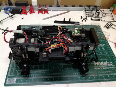
Here you can see the wiring path back to the battery. The cross bar between the lift racks is what will lock into the bed once it is installed. On the right you can see the polycarbonate tubs which cover the electronics pods. 
The rolling chassis is completed by installing the huge wheels and tires which are unique to this model. A real haul truck would have dual rear wheels, but that wouldn't be possible on the model without significantly narrowing the rear axle. This chassis is one heavy beast, but even so there is virtually no suspension compression driving off road. This makes sense since the suspension would be sized based on carrying a full heavy load in the bed. 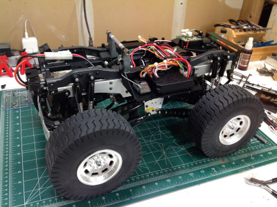
The following user(s) Liked this: Jonny Retro
|
|
|
Please Log in to join the conversation. |
Blakbird's 58268 Mammoth Dump Truck Build 4 years 8 months ago #55985
|
Awesome!
|
|
Please Log in to join the conversation. |

Blakbird's 58268 Mammoth Dump Truck Build 4 years 8 months ago #55986
|
The Mammoth has always been a curiosity to me since it was first introduced. This thread is quite a treat to follow. I enjoy reading such detailed information along with the step-by-step build process.
|
|
|
Please Log in to join the conversation.
Last edit: by Killaj.
|
Blakbird's 58268 Mammoth Dump Truck Build 4 years 8 months ago #55987
I felt the same way about the Mammoth. It was a bit of an enigma since I had never seen a build of it. I'm glad you are enjoying the build. |
|
|
Please Log in to join the conversation. |
|
|
|
Time to create page: 0.264 seconds