TOPIC:

TRF201 Gone Wrong 4 years 3 weeks ago #58767
|
|
Please Log in to join the conversation. |

Time to create page: 0.379 seconds
|
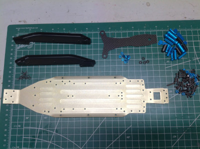
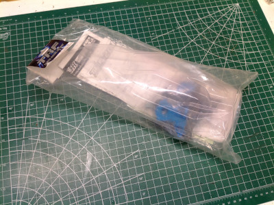
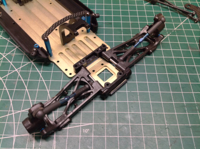
Here are the rest of the parts that came in the box with my TRF201XR kit. These include the parts to convert to the XR extended chassis and also a full set of big bore shocks. You can see the XR conversion parts on the right. The most obvious bit is the new aluminum chassis plate, but there are also a pair of side stiffeners, a carbon battery cover plate, and a bunch of hardware. The primary purpose of this XR conversion is to increase the wheelbase to improve stability.

It only takes one step to assemble the parts that came with the upgrade kit and the result in seen on the left. You can see all the standoff posts in blue anodized aluminum which have been added to the front and rear. From here on, it is just a matter of moving over the parts from the original chassis. On the right you can see that I've added the rear upper deck. It looks a bit odd just floating above the plate on posts like that. 

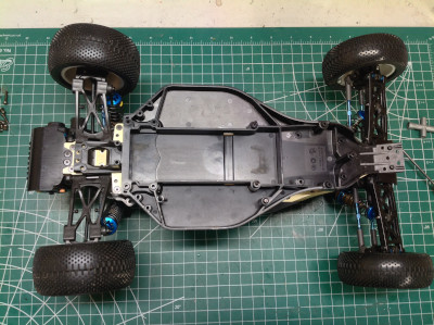
Now the whole rear gearbox and suspension can be moved as shown on the left. The same thing happens for the front suspension as shown on the right. This pretty much completes the conversion. Everything is the same except for the chassis length and material. 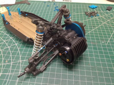
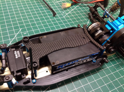
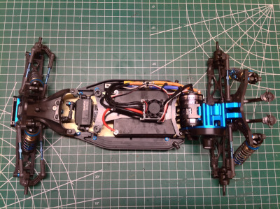
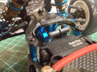
Here you can see the carbon battery plate. This longer chassis has more room and easily fits a hard racing pack. The blue posts can be moved around to allow installation of different sized batteries. I used a low profile servo which allowed me to put the receiver between the battery and the servo. The kit came with a pile of blue spacers to use for different thickness batteries, but I decided to use them to replace the spacers on the hubs just because it looks cool and adds some visual contrast. 

The following user(s) Liked this: stingray-63
|
|
|
Please Log in to join the conversation. |
|
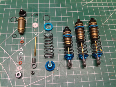
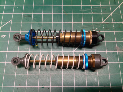
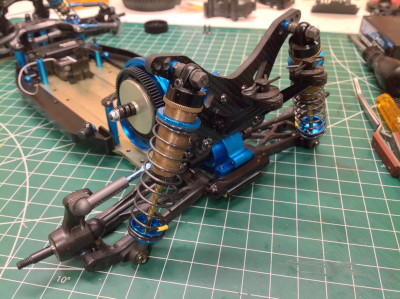
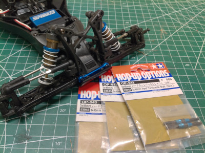
Time to build the "big bore" shocks. In case you are wondering, these have a 12mm bore instead of 10mm. That doesn't sound like a lot, but it results in 44% more volume. The old and new shock types are compared on the right. These shocks build exactly like the smaller set, but you may notice that they now include aluminum spring perches as well. These are really nice shocks. Included with the kit were a full set of front and rear springs with three different rates to choose from. Not knowing any better, I chose the middle stiffness.
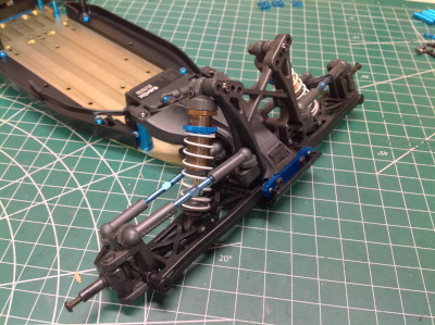
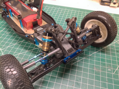
Here the larger shocks have been installed. You can see that they barely fit, especially in the front. There is hardly any clearance between the shock and the links. 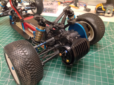
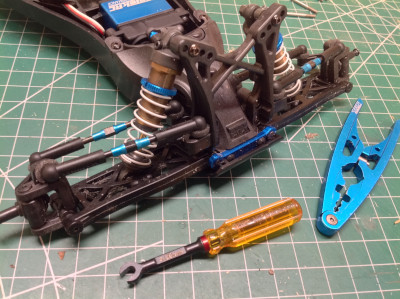
The completed chassis is shown on the left. This is a really beautiful view, if you are someone who appreciates such things. On the right I've inverted the chassis and then laid the old plastic tub on top, lined up at the front. At the back you can see the difference in length. It isn't much, only about 11mm. 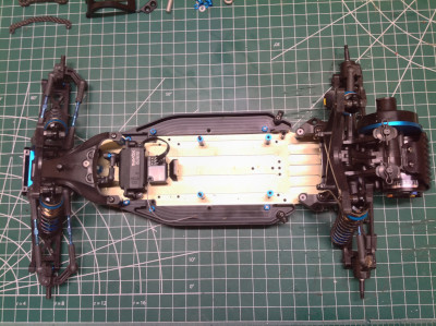
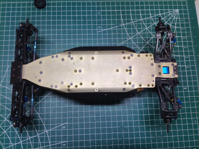
These pictures compare the bottom of the chassis before and after the conversion. The profile of the chassis is quite different. You can see that there are a lot of unused holes on the aluminum chassis which allow for moving around various adjustable components. 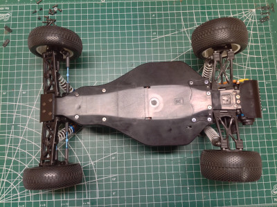

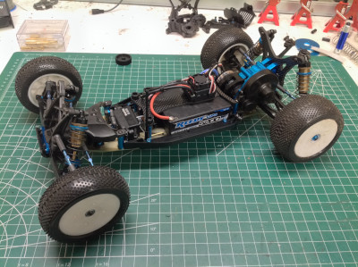
Here I compare the final rolling chassis both before and after the conversion. There are obviously a lot of similarities, but the change in wheelbase is actually pretty obvious if you look for it. There is less width on the new chassis for electronics which means the ESC has to sit up on top of the battery cover. 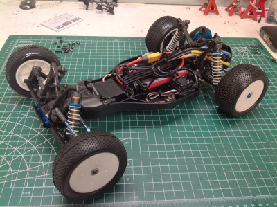
|
|
|
Please Log in to join the conversation. |
|
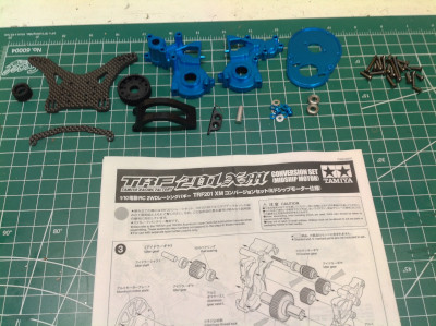
Here is the XM conversion kit which I purchased separately. Although it doesn't come with very many parts, what it does come with is expensive. You can see machined aluminum transmission housings, a heat sink motor mount, an aluminum motor guard, and a carbon fiber shock tower and battery clip. There is also a new body included which is a bit odd since the XM can only be made from the XR which uses the same body. They can, however, be trimmed a bit differently at the back to help hide the motor.
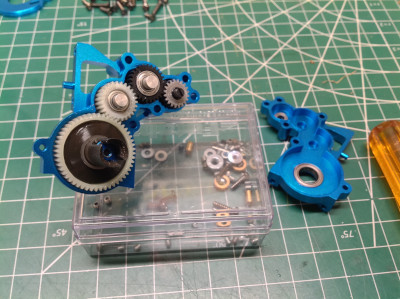
The original TRF201 transmission uses 3 gears. Because the XM flips the transmission around to put it ahead of the rear axle, it also needs to rotate in reverse. To accomplish this an additional idler gear is added. The XM upgrade kit has this gear in black which is supposedly an upgrade in some way, and also includes a new black ring gear for the differential. I didn't want to rebuild the differential so it stayed white. The left hand picture shows the original transmission and the right hand picture shows the XM. It wasn't strictly necessary for the XM to use aluminum instead of carbon reinforced plastic, but I'm glad it does. It looks cool, and it leaves me with an extra stock transmission. 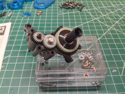
Here is the updated and completed transmission which also includes a new machined motor mount plate. 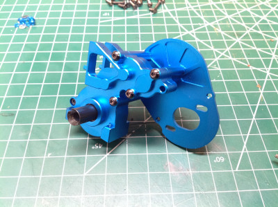
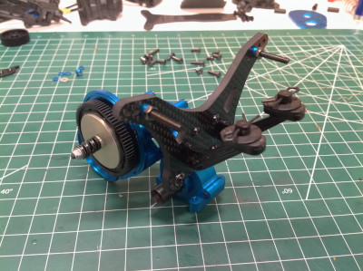
The original rear shock tower sat exactly where the new transmission needs to go, so it had to be replaced. The new shock tower is an incredibly thick (5mm) carbon fiber plate which bolts right to the transmission housing. Part of the reason for the aluminum housing was probably to make this connection nice and strong. The old diagonal brace that spanned the gearbox and shock tower is gone. The wing mounts also connect to the shock tower. 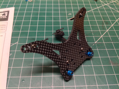
The following user(s) Liked this: stingray-63
|
|
|
Please Log in to join the conversation. |
|
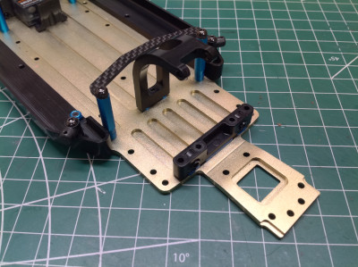
Now the old transmission and rear suspension can be removed to make room for the new. Note that I've added a new curved aluminum motor shroud. The carbon plate ahead of that holds down the back of the battery. The suspension arms connect using the same parts as before, but there is one subtle difference. If you read my build of the original chassis you may recall that the rear uprights were switched left to right (left labeled part installed on right, right labeled part installed on left). Part of the XM conversion is to switch them back the right way around. This effectively moves the ball joint for the upper link from ahead of the upright to behind it. This move will be needed for the new shock tower position.
Now the new transmission assembly can be installed. Obviously the output drive cups need to be in the same position as before to link up with the axles, but the rest of the transmission has been moved well forward. The big bore shocks now sit behind the rear arms instead of ahead of them which moves them much closer to the wing mounts. 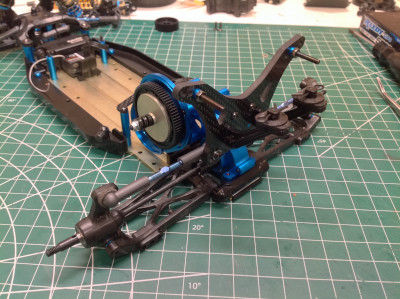
Here are some closer pictures of the new rear assembly with the motor installed. With space on the chassis now taken by the motor, the same long racing pack can no longer be used. The manual suggests using saddle packs but I found that the square pack from my Associated short course truck fits perfectly. This shape battery pack has become quite rare so I may have to change to a different profile in the future. 
|
|
|
Please Log in to join the conversation. |
|
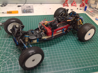
Here I compare the XR and XM chassis variants from above. The front half is exactly the same before and after. In the rear you can see how far back the shock tower has moved. You can also see that the rear upper link and shocks have moved behind the rear suspension. The motor, obviously, has been moved forward. And the new version has a lot more blue.
Here I compare the XR and XM chassis variants from below. The wheelbase is exactly the same but you can see the blue transmission housing through the slot in the rear, and the position of many of the countersunk screws has changed. The XM version was obviously already planned at the time the XR was released because the chassis plate had all the hole options drilled for it.
Here I compare the XR and XM chassis variants from a 3/4 view. The XM has the illusion of being longer because the shock tower has moved back.
I ended up with two bodies because one came with the 42167XR kit and one came with the XM upgrade kit. I sent one off to the painter and used the other for a test fit as shown. It leaves very little room for the ESC but it looks like everything will work. The wing you see in this photo is not correct, I borrowed it from a DT-02 MS just to see how it looks. 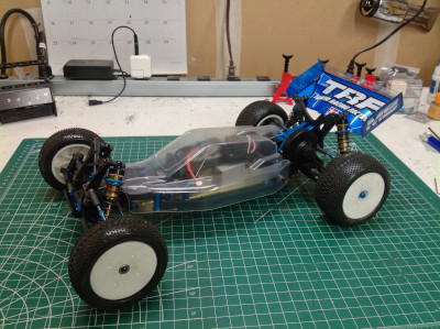
The following user(s) Liked this: stingray-63
|
|
|
Please Log in to join the conversation. |
|
The bodies arrived from the painter. Wow.
The following user(s) Liked this: stingray-63, cjsmidt12
|
|
|
Please Log in to join the conversation. |
|
Perfect
 |
|
Please Log in to join the conversation. |
|
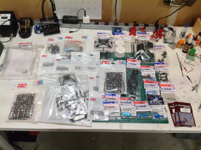
The picture on the left shows all the parts I had left over after finishing the TRF201 XM. Apart from the obvious chassis tub, I had a complete set of shocks, a rear shock tower, a gearbox housing, a motor mount, a battery cover, and lots of hex hardware. It practically looks like a buggy except that all the suspension arms and steering are missing. How hard could it be to complete the model? The answer is on the right which shows the majority of the parts I had to buy to complete the model (a few had not arrived yet when the photo was taken). Many of the parts were reasonably inexpensive, but there were a handful of major exceptions. Let's get started.

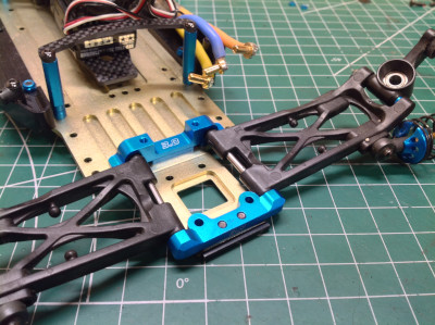
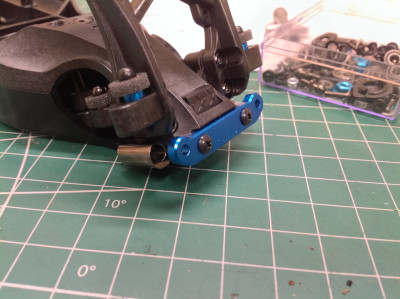
Because I couldn't get everything I needed in exactly the way I needed it, I ended up putting a couple of aluminum upgrades on the XM so I could use the stock plastic parts on the regular 201. The first of these parts were the rear suspension mounts shown on the left. The 3 degree toe angle these produce is equivalent to stock, but they have that cool blue aluminum look. I installed them and then reserved the plastic suspension mounts for the other model. 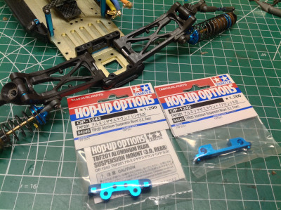
Although all of the plastic parts for the servo saver were available, there was a single bit of hardware, the steering post (BB31), that I couldn't find. Without this it isn't possible to build the steering and it is a custom piece of hardware with no reasonable substitute. However, if I bought the very expensive aluminum racing steering set for the XM which eliminates the need for that part entirely, then I could take the stock steering parts and use them for the other model. The picture on the right shows the racing steering installed. Note that there is no servo saver with this setup. 
With the necessary parts stolen from the XM, I can now start rebuilding the standard 201. On the left you can see the steering system installed which I pilfered from the XM. The next bit I couldn't find available to buy was the front aluminum suspension mount (BB7). This is just a flat plate with a couple of holes, but you can't build the front suspension without it. I found the optional weight block set shown to use instead. This adds 30g of weight over the front wheels for more steering traction and also adds 5 degrees of kickup angle to the front suspension. I didn't necessarily want either of these features, but it was the only way to get the parts I needed. The installed result is shown on the right. 
|
|
|
Please Log in to join the conversation. |
|
Another discontinued set of parts was the blue titanium turnbuckles. I bought the silver titanium parts from 3Racing shown on the left, but I didn't like how they looked since nothing else on the chassis is that color. I found some black and blue turnbuckles from the DF-03 MS to use instead. The length is wrong by 1mm but that was no problem since the ends are adjustable. The result is shown on the right which I think looks much better.
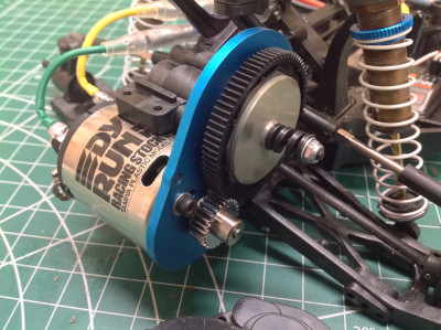
Now I had to decide on electronics. I used a fancy low profile servo on the XM and decided to use a blue anodized ProTek servo on this model mostly because it looks good. Because I used a Tamiya brushless system in the XM, I thought I would use an old Tamiya racing brushed motor in this one. I chose the Dyna Run Racing Stock motor (20T) with the maximum size 27T pinion. It ended up being a really good match for speed and power. In fact, this model was now faster than the 10.5T brushless XM. 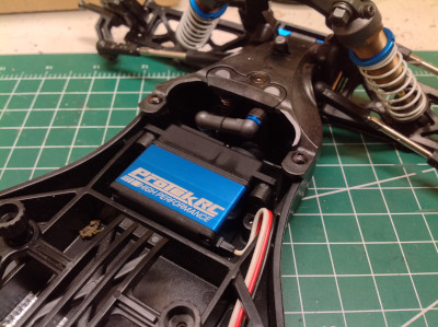
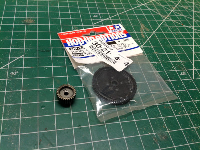
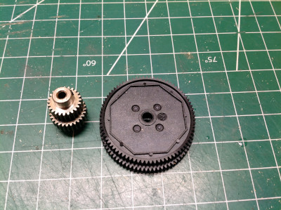
I didn't think it was right for the brushed version to be faster than the brushless so I got the smaller 77T spur gear and went up from a 24 tooth to a 28 tooth pinion on the XM. You can see the difference in size on the right. Let's do some math to see the gear ratios and theoretical wheel speeds. TRF201
The following user(s) Liked this: stingray-63
|
|
|
Please Log in to join the conversation. |
|
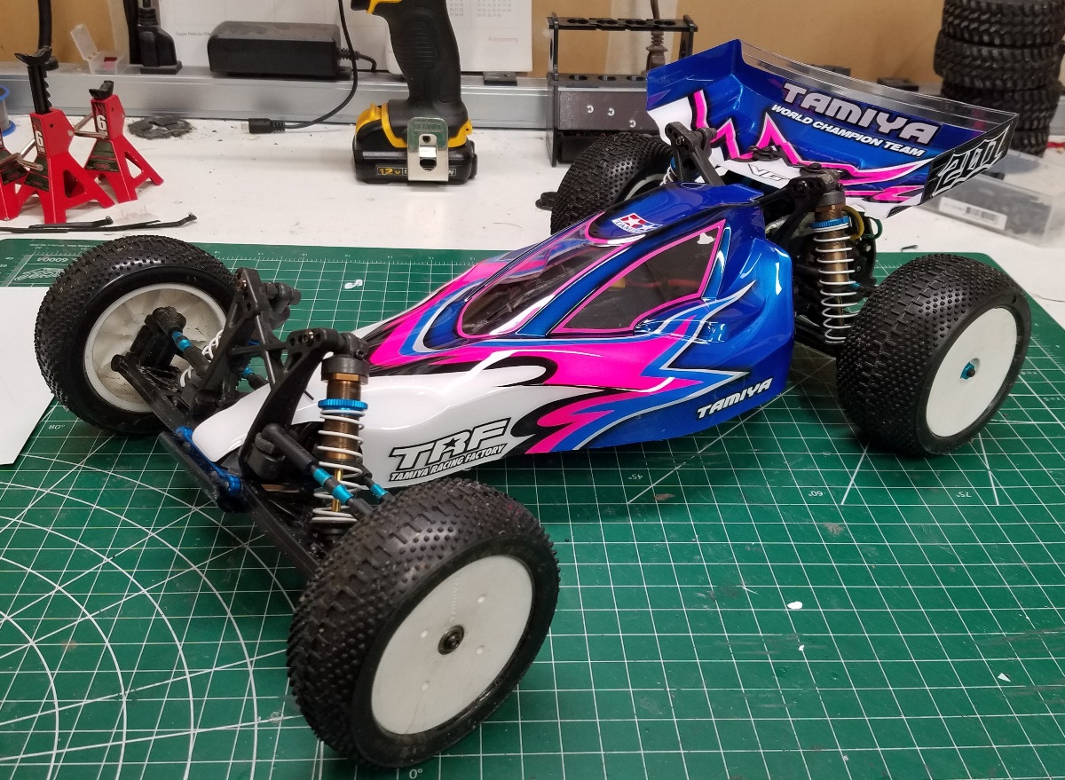
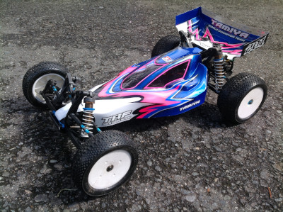
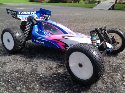
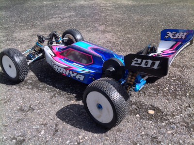
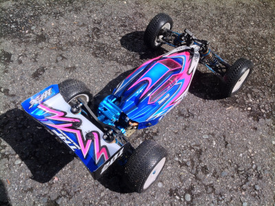
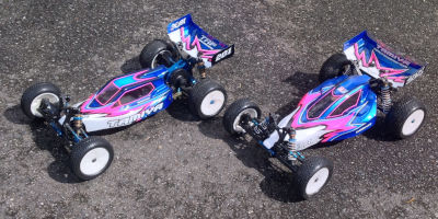
I feel pretty comfortable saying that these are the most beautiful RC models I own. Yes, the Avante and Bruiser are gorgeous in their own way, but they don't have the flair and complexity of this livery. Aside from the livery, the overall shape of the buggies is excellent as well, but I prefer the proportions of the original TRF201 to the XM version.
TRF 201
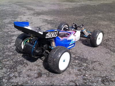
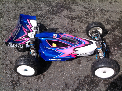
TRF201 XM 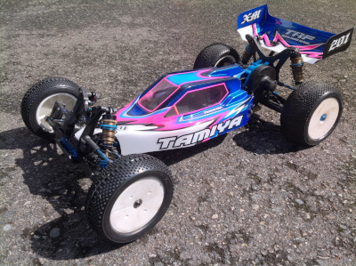

The brothers Karamazov 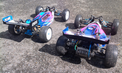
|
|
|
Please Log in to join the conversation. |