TOPIC:
Motor wiring conventions 11 years 6 months ago #14821
|
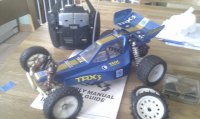
I'm looking to wire up the 380 motor on my son's Brat and I am wondering what the colour convention should be. I have green and yellow wires for the motor with bullet connectors on and the new ESC I have has red and black wires (presumably +ve and -ve).
Now I know I can just reverse the wires if it runs backwards, but I want it to be "right" (and I'm curious too). Also, the Brat manual showns green from the MSC to yellow on the motor and vice versa. Does this imply that the Brat motor runs backwards or are all Tamiya cars like this? Or maybe the 380 motor is wired differently to the 540? Also, presumably I should fit a suppression capacitor to the motor. Any idea on the value of this? The originals are missing. |
|
Please Log in to join the conversation. |
Re: Motor wiring conventions 11 years 6 months ago #14823
|
Forwards/backwards motors - both 540 & 380 motors spin counterclockwise at the business end, the Brat has 2 gear gearbox, so if the motor is spinning forwards, the spur gear is spinning backwards, and the diff (& therefore the wheels) are spinning forwards too ... on an old MSC setup on a Brat the lack of a servo reversing switch on radio gear of the day would be a problem, so I'm guessing that the MSC is operated "backwards" on the Brat (compared to say thr Grasshopper, I think I'm right here), so the motor wiring has to be reversed ... TBH I wouldn't worry about it - whatever setup you need to make the wheels spin forwards when you puch the left stick up is the "right" one.
Capacitors - 4.7nf is the usual value - e.g. ebay item 120918426499 ") |
|
Please Log in to join the conversation. |

Re: Motor wiring conventions 11 years 6 months ago #14835
|
The capacitors are "snubbers" - they reduce arcing & voltage spikes. Main reasons for fitting - to reduce brush/comm wear, to reduce nuisance interference (TVs, 27MHzam radio) & to protect sensitive electronics (ESCs) against high voltage spikes. Note that 1:1 car "suppressors" are high-value resistors to reduce high voltage related interference on TVs & radios, & capacitor-resistor networks to reduce spike-related interference from lower voltage arcing, being detected in hardwired components within the vehicle. Capacitor-resistor (RC) networks are what is usually used for snubbing & anti-interference applications (usually 100ohm resistor in series with 0.1uF cap)
Value isn't hugely important, the greater the capacitive value, the larger the damping effect. They have to be high voltage non-polarised types due to the application (ie, electrolytics won't work) which will limit your choice for maximum value. Some say the value is important as they filter interference at a particular frequency, but in this day & age the protection of ESCs is their main use so selective frequency filtering doesn't really come into it, especially as this only applies at certain motor rpms, not throughout the rev range. To be safe, use the value the ESC manufacturer recommends. I personally use 0.1uF epoxy capacitors (Unless specified otherwise) as they're cheap & easy to come by - in recent times, "odd" value components are being phased out, decimal values is what's going to be left (1,10,100 etc) "Correct" rotation of silvercan motors - if you look down the holes nearest the endbell of a cheapy motor, you'll see that the brushes are held in place with springy metal plates. You'll also see that in most cases they approach the comm from opposite directions. Correct rotation is when the comm is spinning away from the root of these springy plates, so that the brushes drag over the spinning comm. In reverse rotation, the comm spins towards the roots of these plates, the brushes effectively "digging in" to the comm, increasing brush & comm wear due to the increased brush pressure. Although in reality it doesn't happen, there is also the potential for the brushes to "snag" in the slots in the comm when running backwards. You have probably noticed that even non-tuned silvercan motors run faster in one direction than the other. I haven't actually checked, but I'd say you'd find that the motor spins faster in "reverse" - You can see this effect with a worn out modified motor. When the comm has gone out of shape, the brushes "bounce" & don't contact it very well. Increasing the brush spring pressure makes the motor spin faster, but also wears the brushes & comm a lot faster too. If you're looking for "correct" wiring colours for a particular model, I'd say you need to abandon the idea of (eg) "yellow = +ve" but instead look at the interconnection in the manual (eg yellow-to-green or yellow-to-yellow) for that particular model, & ask someone "which way does the MSC move to give forward travel?" & wire your motor to suit. This would make the hardware "correct as Tamiya intended it to be", but there's a 50% chance that forward on your tranny stick will make the car go backwards. For silvercans & MSCs in the real world, +ve & -ve doesn't really matter, & you'll probably find you can't get "Correct MSC direction" "Correct wiring colours" & "Correct motor direction" to tally up, let alone tally up AND have the car go forward when you prod the stick! For ESCs, forward HAS to be correct, as the current handling for reverse is less. Getting the stick forward, car forward relationship "wrong" can lead to fried ESC &/or forward-instant reverse, reverse-brake-forward operation (ie operation is reversed). For tuned/modified motors, rotation direction is important. Check that "Tuned direction" matches "Car forward" - for some gearboxes (Or motor orientations) this is impossible to achieve unless you buy a special "reverse tuned" motor or one that can be adjusted to be tuned in an opposite direction. Perfect example of this is Clodbuster, where 1x motor has to be tuned forwards, & 1x tuned backwards, to give overall improvement of forward-running of the car
Custom F2
...
Hilux crossmember drawing
...
F2 axle drawing
...
Quattro radio lid
...
Holiday Buggy motor bracket drawing
...
Quattro resto
...
HitnMiss engine
...
Wild Willy resto
...
Mardave Cobra resto
...
Thunder Dragon resto
...
Grasshopper resto
...
XR311 resto
...
Modded XR311
...
Carbon 25th scratch build
|
|
|
Please Log in to join the conversation. |

Re: Motor wiring conventions 11 years 6 months ago #14847
|
Thanks for the info. Obviously you are constrained by the gearing of the car and the construction of the motor as to which direction the current has to flow. I was just wondering if there was a convention as to which colour wire went on which terminal of the motor.
I wired it up and of course it ran backwards! Sod's law in play there. Just a simple matter of swapping the bullet connectors to make it right. The other thing to consider with ESCs is regenerative braking. I *think* this only works in forwards. Certainly the motor seemed to stop faster in that direction when I span the wheels in the air. |
|
Please Log in to join the conversation. |
Re: Motor wiring conventions 11 years 6 months ago #14851
|
Other than testing motors, another clue to existence of a motor wiring convention, would be to look at various models/manuals to see if cars with 2-stage gearing & RHS motors (eg Grasshopper) only have the yellow-to-green wiring mismatch, & cars with 2-stage gearing & LHS motors (eg Astute?) yellow-to-yellow matched wiring, tally to show "Yellow always goes to this terminal to make the motor go this way when you apply +ve to it".
Just had a bit of a duh moment - the way an MSC is built, it will always connect battery +ve to yellow when turning the plate one way, & to green turning it the other. IF the LHS/RHS motor thing above applies, there lies the answer.... now, how could we find out which way the MSC plate turns to give "forward"? - I think I've seen it marked in some manuals, in the setting up the MSC section. I'll have a proper look when I get more time. Regenerative braking & ESCs... This is a grey area for me. I know that if you short the wires of a spinning motor, it stops almost instantly (By shorting the wires I mean disconnect them from the power first!). I guess this is because an unpowered but spinning motor is a generator... & by shorting the wires, you are asking said generator to deliver all available energy into a huge load (The wire is a very low value resistor, ie a huge current sink), so stored kinetic energy of the spinning rotor gets turned instantly into heat in the wire & the rotor stops dead. Early MSCs used the "Shorting the motor through a low resistance" method for braking, & I always assumed it would be the same thing with ESCs, after all, FETs are just electronic switches, so couldn't they be told to short the motor output, & sink the energy as heat through their heatsinks? Also, a FET isn't just an on/off switch, they will conduct by varying amounts, so in theory you could vary how much of a short you were creating, to give varying degrees of braking... I could be talking absolute rubbish here, truth is, I've never investigated how that part of an ESC works
Custom F2
...
Hilux crossmember drawing
...
F2 axle drawing
...
Quattro radio lid
...
Holiday Buggy motor bracket drawing
...
Quattro resto
...
HitnMiss engine
...
Wild Willy resto
...
Mardave Cobra resto
...
Thunder Dragon resto
...
Grasshopper resto
...
XR311 resto
...
Modded XR311
...
Carbon 25th scratch build
|
|
|
Please Log in to join the conversation. |
Re: Motor wiring conventions 11 years 6 months ago #14852
|
Missed the point completely there, didn't I....
Yeah, braking & ESCs from a wiring point of view - most ESCs have a distinct operating order - full reverse to full forward stick, ESC goes "backwards>instant forwards". Full forward to full reverse stick, ESC goes "forwards>braking>(delay)>backwards". I think the lack of any delay going full back to full forward is because of the higher current capability of the forward FET arrangement (More of them, or different components) I think "Braking" is the FETs being energised in such a way that both forward & reverse components are conducting just enough to give a degree of semi motor wire shorting, whilst at the same time, keeping this current flow within acceptable levels that the FETs can cope with. I think the delay between braking & reverse is to ensure there's no chance of poking high forward current through the motor & back up the other wire into the bank of less hardy reverse FETs, which are likely to still be semi-conducting from the braking operation, ie FETs don't like reverse current flow through them, so the delay ensures they don't see any. Getting the ESC forwards & backwards muddled & compensating by swapping wires or using the tranny servo reversers is bad news. It allows the reverse FETs to see more current that they should, & higher reverse flows than they can cope with. Another giveaway as to what's forward & whats backwards - some (Not all) ESCs have a restricted full reverse current, ie even with a silvercan, they'll drive the motor slower (& with less power) in reverse
Custom F2
...
Hilux crossmember drawing
...
F2 axle drawing
...
Quattro radio lid
...
Holiday Buggy motor bracket drawing
...
Quattro resto
...
HitnMiss engine
...
Wild Willy resto
...
Mardave Cobra resto
...
Thunder Dragon resto
...
Grasshopper resto
...
XR311 resto
...
Modded XR311
...
Carbon 25th scratch build
|
|
|
Please Log in to join the conversation. |
Re: Motor wiring conventions 11 years 6 months ago #14858
|
Well, I am guessing that the motors will all be wired up the same way from the factory due to production practices and the fact that it would render the instructions useless if they weren't. So, let's assume that's the case.
Second - the "correct" motor rotation for forwards motion will depend on whether there is an odd or even number of gears between the motor and wheels (edit: and whether the motor is LHS or RHS). I kinda assumed that all models would have the same rotation, but apparently not. The Brat instructions definitely show yellow-green and green-yellow wiring which suggests to me that the motor rotates in the "wrong" direction (maybe "non conventional" would be a better way to put it). I suppose we could look at a load of different instruction manual and compare motor wiring and number of gears, but an easier way would be to find a factory fresh motor and connect it direct to a battery and see which way it spins. We would then know the correct convention. Oh, and on ESCs, I think you are right about the braking. My Traxxas has a forwards-only ESC and it has variable braking depending on how far back you pull the stick, so it must be modulated by the FETs. |
|
Please Log in to join the conversation.
Last edit: by Martin Bell.
|
Re: Motor wiring conventions 11 years 6 months ago #14859
|
My comments about motor rotation direction came from observation of several motors from my spares box, including 3 380s ... positive/negative connection on motors is defined by the marking of the endbell to indicate the +ve terminal - there's a pip, sometimes red, sometimes recessed, sometimes sticking out approx 30 degrees away from one of the terminals. |
|
Please Log in to join the conversation. |
Re: Motor wiring conventions 11 years 6 months ago #14890
|
Good observations there Jonny! I take it you mean on the metal-ended motors? Are there any such markings on the older plastic-ended ones?
Could you do us a quick test, connect battery +ve to the marked motor +ve, to see which way it spins, away or toward the roots of the brush spring plate thingies? Ta ta ta... Not so sure about wires being attached at the factory - yes it could be that Mabuchi (Or whoever) get an order to supply say 1000 motors for Tamiya, & the "Tamiya spec" is to have green/yellow wires & capacitors fitted, (eg) yellow to +ve. Whereas the rest of their motors are dispatched with no wires, or wiring as per other client's specs. OR it might be that Tamiya spin the motors up to check direction & add the wires etc themselves. Whether or not the wires always get fitted (eg) yellow = +ve, remains to be proven. The "Test a factory-fresh motor" idea is a good one, but I suggest testing a "sample" of mixed old/new/540/380 to prove at the same time they're also all wired the same way & always have been, rather than "This particular one is wired like this". The motors as a mechanical thing have a "correct" rotation when they leave the factory, the same as a car engine (Re the brush spring plates) & are modified by the user (Or rather next manufacturer) to suit the application. In the case of the car engine, you change the camshafts to make it run in the opposite direction. In the case of a mundane silvercan motor, it'll already run the other way without modification so Tamiya don't worry about it, whether it's theoretically correct or not for the mechanical thing. What I'm trying to say is, right or wrong thing to do, it functions when used "not as intended" without any obvious ill-effects, so you can't pin "Correct rotation" down to "cos this is how it works with the gearbox" There definately will be models out there whose motor orientation & gearbox configuration equate to the motor running backwards (Theoretically not as intended) to give normal forward operation of the model. Because it's only a toy, & it doesn't matter....
Custom F2
...
Hilux crossmember drawing
...
F2 axle drawing
...
Quattro radio lid
...
Holiday Buggy motor bracket drawing
...
Quattro resto
...
HitnMiss engine
...
Wild Willy resto
...
Mardave Cobra resto
...
Thunder Dragon resto
...
Grasshopper resto
...
XR311 resto
...
Modded XR311
...
Carbon 25th scratch build
|
|
|
Please Log in to join the conversation. |
Re: Motor wiring conventions 11 years 6 months ago #14893
|
I'll dig some more motors out tomorrow, but off the top of my head I know the black plastic endbell Mabuchis from the Willy Willy M38 era are definately marked - they have a dimple moulded into the plastic 30 degrees from the +ve terminal |
|
Please Log in to join the conversation. |
Time to create page: 0.171 seconds