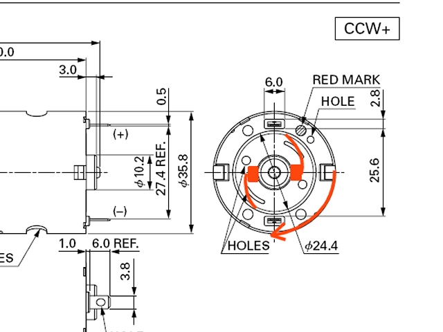
Yep, the terminals are marked for reference, but as far as I know there's no "standard" that says "All DC brushed motors must be built to preferentially run clockwise, terminals should be polarity marked to give this preferential rotation" - I think individual manufacturers polarity mark the terminals so that the motors run in the direction that is preferred with respect to how that manufacturer builds their particular motors, the direction that would give best service life with least potential faults.
Like you say, the electrons don't care which way they're travelling in the wire or what colour the wire is, they're just making the magnetism. What's important direction-wise is how the static connection to rotating parts will behave in a mechanical way. Of course the electrons have to travel in a certain direction to cause rotation in a certain direction, but with respect to polarity markings, that will be determined by how the motor is wound. Of course I could be talking rubbish, but it makes sense to me even if it doesn't apply!
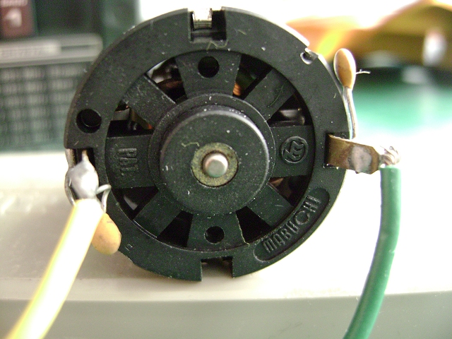
The way I'm looking at it is this - consider an upturned bicycle. Spin a wheel, then, with the wheel spinning away from you, hold a stick (Facing away from you) against the tyre - the stick just rubs on the tyre. If you then do the same thing, but with the wheel spinning towards you, the stick digs into the tyre & breaks, right? - That's how I'm looking at the brush arrangement in a cheapy silvercan, & that's why I'm saying that there is a preferred rotation direction for a motor with this brush setup. Ok, the motor will run both ways, but theoretically it should only be run in the preferred direction, hence the polarity marks? Like I said, I might just be the first person sad enough to have ever thought about it & it doesn't actually matter...
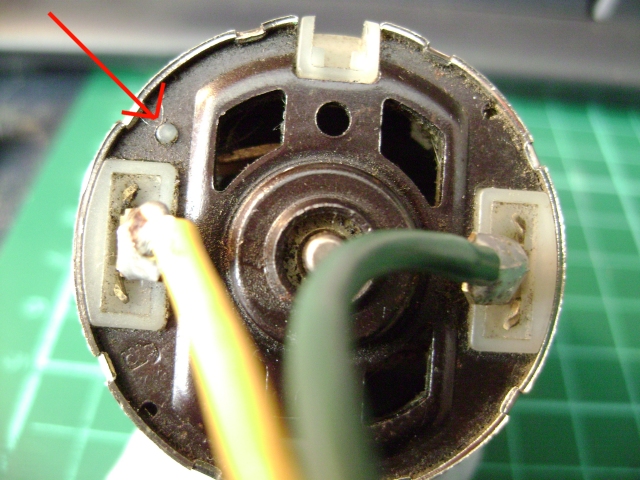
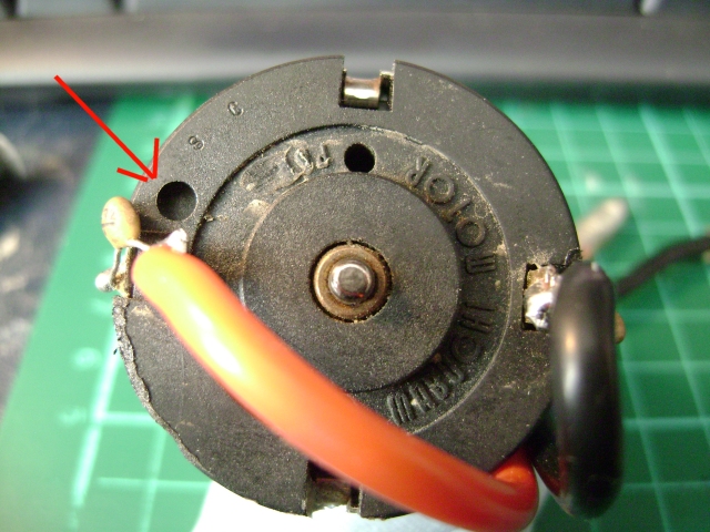
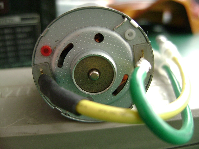
We don't actually know if "yellow always = +ve" or if the yellow & green are attached in such a way as to give clockwise rotation when the motor is RHS mounted, & the only way to find out is to look at a selection of old/new motors from different manufacturers (Johnson, Mabuchi etc) to see if they're all wired the same way. (Pause for thought) It might even be that Mabuchi/Johnson etc are supplying batches of clockwise/anticlockwise motors to suit the different Tamiya motor/gearbox setups, but unless we actually look, how would we ever know?
The assumption that the yellow/green connection instruction in the manual is "right" is a dangerous one. Tamiya don't know what radio gear you're using, if the servos turn left or right with "Stick up" or if there's any provision with your gear to reverse the servo action. eg as Jonny said, back in the oldern days, you'd connect everything up as per the manual, only to find that everything worked backwards, & the only way to correct it was to swap the wires to be the exact opposite of what the manual was instructing you to do. There is definately no standard "forward stick = clockwise servo rotation", it depends on the particular radio &/or manufacturer. eg Acoms AP427 - I can tell you that on some of these sets, but not all, the throttle channel works in reverse to the AP227, & I can also tell you that some sets were supplied with servos that work in reverse to others (Re AS2 & AS3). Pick up a vintage Sanwa set of similar age, & depending on the model, will work in reverse to an Acoms set.
Phew... getting back to the point... Look in the Brat manual, to see if the "Setting up the MSC" bit actually specifies which way the MSC turns to give car-forward. Trace battery +ve (Red) through the MSC contacts in "forward" to see what colour wire +ve comes out of. Connect green/yellow motor wires to the MSC green/yellow wires, as per the manual. Solder the motor wires to the motor whichever way around causes your wheels to go forward. This at least would have the wiring/colours "correct" as per the manual. Then all you'd have to do is use your tranny servo reversing switches to give "forward stick = car forward".
If you're tranny hasn't got servo reversers, swap the motor connections - politically, this is still correct as it would be the situation you'd probably be faced with back in the early 80s, unless you owned some new Futaba Attack radio!


")